Facebook
 Google
 GitHub
 Linkedin
Implementing Isolated Bidirectional Power Converters
This article explores the implementation of isolated and bidirectional DC-to-DC power transfer by adapting a dedicated digital controller to work in reverse power transfer in addition to its standard forward power transfer function. System modeling, circuit design and simulation, and experimental work are presented to validate the theoretical concepts.
This article is published by EEPower as part of an exclusive digital content partnership with Bodo’s Power Systems.
Modular battery-based energy storage systems are key technologies for the construction of a green energy ecosystem, as they assist in the effective utilization of renewable electricity. An increasingly popular application is second-life battery energy storage systems. In this submarket, up to 80% of the discarded batteries are expected to be repurposed into energy storage systems for stationary grid services, hence increasing the useful life of batteries from five years up to 15 years. These systems are expected to add up to 1 TWh to the grid capacity in 2030. This emerging application is bound to gain more importance within the energy market in the near future.
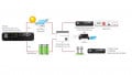
A typical implementation consists of different stacks of battery modules transferring their energy to the centralized AC or DC buses (for some form of subsequent energy dispatched to loads) via power converters. The challenge with this type of system is that each module has different chemistries, capacities, and aging profiles. In a traditional modular topology, the weakest module affects the total usable capacity of the full stack (Figure 1).
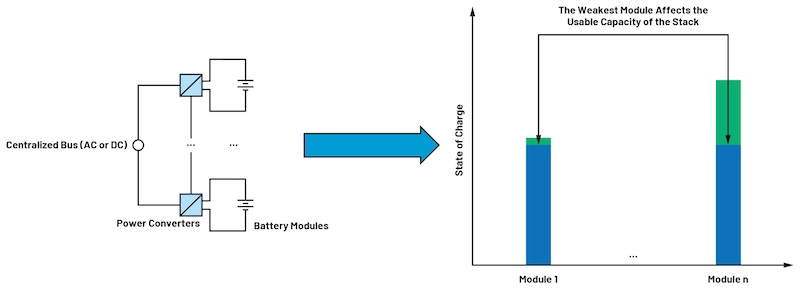
Figure 1. The challenge with modular energy storage systems. Image used courtesy of Bodo’s Power Systems [PDF]
To tackle this limitation, in the architecture shown in Figure 2, the energy in the stack is transferred to a common, intermediate DC bus via individual DC-to-DC converters for each battery module. This energy is then used to support a centralized medium voltage (MV) AC or DC bus via a main power converter. The voltage and power levels in Figure 2 have been chosen based on typical figures from energy storage systems in the market: 48 V battery modules, 400 V (DC) intermediate DC buses, more than 20 kW (high power) main power converters, and up to 1500 V centralized buses.
In Figure 2, because the ground references of each module in the stack are different, isolation is needed to implement the individual DC-to-DC converters for each battery module. In addition, for supporting hybrid systems like second-life battery energy storage systems, each of these converters must also be able to transfer power bidirectionally. In this way, independent charge/discharge of each module and charge balancing can be easily achieved. Therefore, the central blocks of the application herewith discussed are isolated and bidirectional DC-to-DC converters.
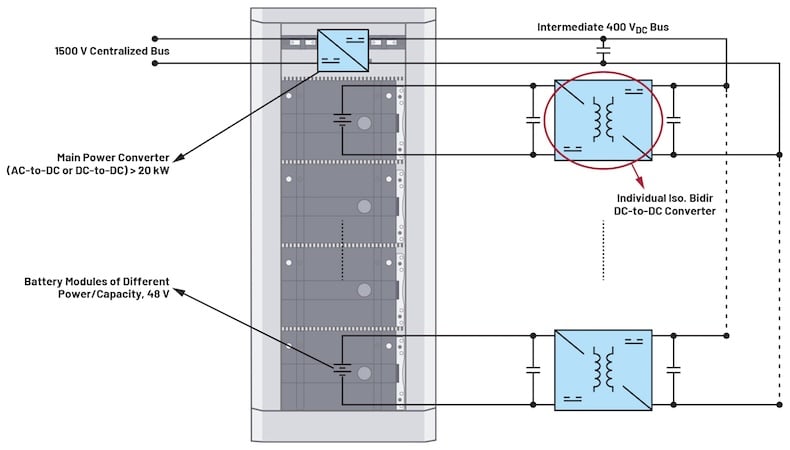
Figure 2. A modular battery-based ESS. Image used courtesy of Bodo’s Power Systems [PDF]
Dedicated Digital Controllers for Power Conversion Applications
For the control of the switching devices in high-power DC-to-DC converters (larger than 1 kW), digital control is the current standard in the industry, and it is typically based on microcontroller units (MCU). Despite this, an increased focus on functional safety (FS) across industrial applications could favor the case for using dedicated digital controllers instead. From the system design perspective, an easier FS certification is particularly beneficial in modular implementations as it facilitates the design process and, therefore, reduces the overall time to revenue. Some of the reasons that favor the case of dedicated digital controllers over MCUs include:
- Microcontrollers depend on software, which, until the development of IEC 61508, was not allowed in a safety system because it was considered unstable due to the number of states it contained. Hence, a lot of the FS effort with an MCU goes into the process used to develop the software.
- The MCU itself would have to be certified in addition to the software. Although dedicated digital controllers (as configurable devices) are still data-driven, their configuration process involves a limited variability language (LVL) as opposed to a full variability language (FVL), which is distinctive of MCUs.
- As a sequential digital machine, the functions of a dedicated digital controller can be completely verified by testing, which is generally not possible for the software in an MCU. As a result, the core safety functions are integrated by the device when using a dedicated controller.
- Added safety functions for MCU implementations might need considerable additional hardware compared to the integrated safety functions in a dedicated controller. This is prone to adding more complexity to the system level when using failure modes, effects, and diagnostic analysis (FMEDA).
- When using a dedicated controller, additional safety (if needed) can be programmed in an external MCU, usually available at the system level.
The ADP1055 by Analog Devices is a digital controller especially built for isolated DC-to-DC high-power conversion and offers a range of features for improved efficiency and safety. These functions include programmable overcurrent protection (OCP), overvoltage protection (OVP), undervoltage lockout (UVLO), and overtemperature (OTP). Like many equivalent off-the-shelf parts in the market, this controller is designed for energy transfer in one direction only—that is, FPT. To achieve a bidirectional operation, the application with the controller must be adapted to work also in RPT. The next section explores one important aspect in both FPT and RPT modes, which is necessary to understand prior to the process of adaption. This is the efficiency of the target DC-to-DC converter.
Achieving Efficient Energy Conversion
Among the different technologies available for isolated and bidirectional power transfer in DC, the architecture in Figure 3a is one of the most used commercially due to its simplicity of implementation.
This topology can be seen either as a voltage-fed full bridge to a center-tap synchronous rectifier in FPT or as a current-fed push-pull converter to a full-bridge synchronous rectifier in RPT. A case study with 400 V (DC) in the primary (DC bus) and 48 V (DC) in the secondary (battery module) for high power levels larger than 1 kW is depicted to illustrate the common challenges of the application. LTspice was used to simulate the operation with typical wide band gap (WBG) power devices switching at 100 kHz. The parameters used in the simulation are depicted in Table 1.
Table 1. Simulation Study Parameters
| Circuit Parameter | Value |
| Rated DC Bus Voltage | VBUS = 400 V (DC) |
| Rated Battery Voltage | VBATT = 48 V (DC) |
| Switches MA, MB, MC, MD | SCT3017AL 650 V/18 A SiC MOSFETs |
| Switches MSR1, MSR2, MCLAMP | IPB065N15N3 150 V/136 A MOSFETs |
| Transformer | Np/Ns = 6:1; Lm = 50 µH; LLEAK =0.1 to 1 µH |
| Choke Inductor | Lo = 50 µH |
| Clamp Capacitor | CCLAMP = 1 µF |
| Bus Capacitor | Co = 10 µF |
| Switching Frequency | 100 kHz (effective 200 kHz) |
The results in Figure 3b show a rapid decrease in efficiency for higher power levels when regular hard-switching (HS) PWM is used. This is accentuated when comparing RPT with FTP. To improve operation, two main loss mechanisms are identified, which can be mitigated with the corresponding switching techniques described next.
Figure 3. Power conversion topology simulation: (a) model and (b) efficiencies, in standard operation. Image used courtesy of Bodo’s Power Systems [PDF]
Soft Switching
Figure 4a shows how in this low leakage inductance design, primary switches MA and MB do not turn off fast at the passive-to-active switching transitions when using regular PWM. This situation creates higher switching losses in the overall system. In this case, the use of phase-shifted (PS) PWM, like zero-voltage switching (ZVS) or soft-switching, helps bring the drain-to-source voltages down to zero during these transitions. This can be done by providing appropriate, load-dependent dead times that allow the full discharge of the drain-to-source capacitances of the switches. The results of applying PS are shown in Figure 4b.
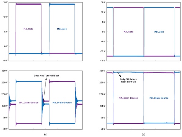
Figure 4. Primary switches passive-to-active transitions with (a) HS and (b) PS PWM. Image used courtesy of Bodo’s Power Systems [PDF]
Active Clamping
Figure 5a shows how during the turn-off of the secondary switches MR1 and MR2, a large spike and ringing are observed on their drain-to-source voltages. These transient events endanger the integrity of the switch, waste energy, and contribute to electromagnetic interference. Digitally controlled active clamping using an additional switch (for example, with MCLAMP in Figure 3) is the best alternative to alleviate the negative effects of this spike. This can further increase the efficiency of this architecture. The results of applying a form of active clamping are shown in Figure 5b.
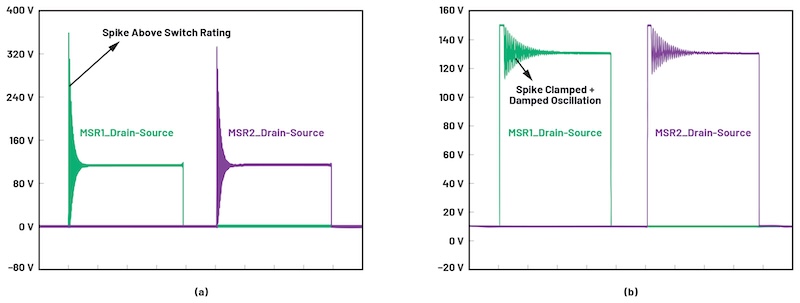
Figure 5. Primary switches passive-to-active transitions with (a) HS and (b) PS PWM. Image used courtesy of Bodo’s Power Systems [PDF]
Implementing these strategies increased the converter's efficiency from less than 80% to more than 90% at 5 kW in RPT. These simulation studies also predict similar efficiencies for both FPT and RPT, as shown in Figure 3b.
To implement these switching functions, the ADP1055 offers six programmable PWM outputs to form the timing of the switches and two GPIOs configurable as active clamp snubbers. Both functions are easily programmed within a user-friendly GUI. The benefits of these and other functions of this digital controller can be further studied in the ADP1055 EVALZ user guide, where the standard FPT application is considered.
Once the mechanisms for achieving viable levels of efficiency have been identified, which are suitable for both FPT and RPT modes in this application, the adaption to RPT is finally explored next.
Reverse Power Transfer Adaption
In order to demonstrate the operation of the application under study in RPT, a low voltage (LV) experimental setup was created as a proof of concept. This setup was based on the hardware in the ADP1055 EVALZ user guide, originally designed for 48 VDC to 12 VDC/240 W FPT, using the ADP1055 as the main controller at switching frequency fSW = 125 kHz, as a standard case. The RPT operation adaption then involved adequate hardware and software modifications. Figure 6 (top) shows the proposed signal chain on the hardware side for this task, with the following highlights:
- The four primary switches are turned on and off using two matching ADuM3223 isolated half-bridge gate drivers. The precise timing characteristics (54 ns max. isolator and driver propagation delay) of these drivers accurately reflect the control signals into the PWM.
- The isolated power supply unit in the ADP1055-EVALZ user guide is rewired and supplemented with an ancillary precision LDO (ADP1720) to account for the two ground references in the system and to energize all the application's different ICs.
- On the measurement side, the terminals for current measurement on the shunt resistance are swapped so that the output current in the secondary of the transformer of the overall converter is measured in the right direction on terminals CS2+ and CS2– of the controller.
- The ADuM4195 isolated amplifier provides a safe and accurate measurement of the DC bus voltage, which is the output variable in RPT mode, in contrast to FPT, where the battery-side voltage was the controlled output.
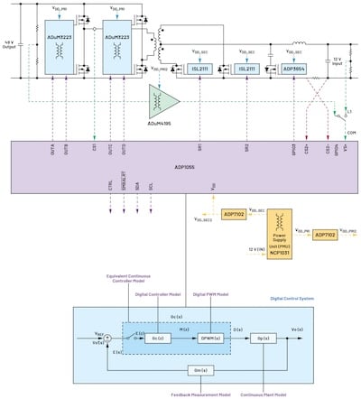
Figure 6. Signal chain to adapt RPT with a dedicated digital controller. Image used courtesy of Bodo’s Power Systems [PDF]
The ADuM4195-based measurement scheme is one of the most important additions to the control loop hardware. Besides a safe 5 kV isolation voltage (from the high voltage primary to the LV control side), broad input range of up to 4.3 V, and around 0.5% accuracy at its reference voltage, the ADuM4195 features a high minimum bandwidth of 200 kHz. This allows faster loop operation for better transient response than the typical shunt regulator and optocoupler solutions, which is essential for the operation of the application at its 125 kHz switching frequency. Figure 7 shows the final experimental setup, with the hardware additions of Figure 6 implemented in an ADuM4195-based measurement daughter card, which was added to the original evaluation board in the ADP1055 EVALZ user guide.
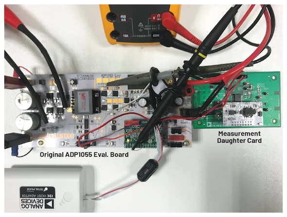
Figure 7. Experimental setup for the RPT proof of concept. Image used courtesy of Bodo’s Power Systems [PDF]
Figure 6 (bottom) also depicts the configuration performed on the software side for RPT adaption. The digital control system was studied in depth. The results are summarized in the descriptive blocks of the process, as follows:
- The right steady-state response was achieved by changing the PWM settings to have duty cycle changes proportional to the secondary inductor charging. This is according to the boost-type operation that the architecture has in RPT mode.
- The transfer function of the plant in the Laplace domain, Gp(s), was identified with the AC small-signal equivalent circuit technique, accounting for the LCL output filter of the design on the ADP1055-EVALZ user guide. Different from the FPT, the plant response in RPT is that of a second-order system with a righthand side zero (RHZ), typical of a boost converter in CCM. Note that a system of this type is intrinsically unstable and will need a reduction of bandwidth in the error amplifier.
- The feedback measurement Gm(s) was modeled upon the frequency response of the ADuM4195 working as an isolated follower (Figure 8) using the MATLAB® System Identification Toolbox. A dominant pole around 200 kHz was confirmed, so a fast response that remains above the control system’s target bandwidth (around 10% of the 250 kHz observable double frequency) is guaranteed.
- The option to add a pole to the standard digital compensator of the controller was taken, resulting in reduced bandwidth in the overall control system, necessary in this nonminimum phase boost-like converter plant. Thus, the digital controller in Equation 1 was used (constants as defined in the ADP1055 user guide).
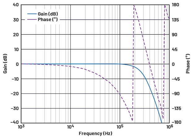
Figure 8. Frequency response of the ADuM4195. Image used courtesy of Bodo’s Power Systems [PDF]
In order to keep the analysis in the Laplace domain, a continuous-time model Gc(s) of Gc(z) was created, according to digital control theory. Thus, a computational delay was added first (× z-1), and the final representation in continuous time was achieved by using:
(a) the Tustin approximation
\[\Bigg(z=\frac{(4f_{sw}+s)}{(4f_{sw}-s)}\Bigg)\]
and
(b) the Padé approximation to model the discrete PWM (DPWM) delay (of Tsa/2=1/4fsw)
So that, finally, the open-loop transfer function Gol(s) = Gp(s) Gm(s) Gc(s) was studied for the design a stable response, using the MATLAB Control System Designer as a regular continuous-time control loop.
One of the main observations in this exercise is that if the same control constants as for FPT were used, the response in RPT would be unstable. Hence, a proper design of the final values of the constants in Gc(s) is vital for a reliable operation. Once a stable open-loop transfer function was achieved by design, the controller was transformed back into the digital domain. Figure 9 (left) shows the frequency response of the designed digital filter Gc(z), which can be easily configured graphically with the GUI of the ADP1055 in Figure 9 (right).

Figure 9. Digital filter response configured on the ADP1055. Image used courtesy of Bodo’s Power Systems [PDF]
The functions for increased efficiency studied in the previous section (PS PWM with adaptive dead times and active clamping) were also configured. Experimentally, it was observed that to achieve proper ZVS in the active-to-passive transitions for RPT, it was necessary to modify the dead times in the PWM sequence. Namely, the turn-on of the secondary switches was modified to happen before each transition from active to passive intervals to allow for current reversal.
The adaption to RPT was tested successfully with 48 V obtained in the primary from an input of 12 V in the secondary. Outstanding output voltage regulation to load and input-voltage changes, respectively, of 0.1% and 0.02% relative standard deviation (RSTDEV) were achieved, as shown in Figure 10a. Figure 10b and Figure 10c show the conversion efficiency and the step response to a 50% load change, respectively. The efficiency levels in RPT are similar to FPT mode, with a peak of 94% at midpower range, in both cases. The step response parameters (overshoot and settling time) are (1%; 1.5 ms) in RPT compared to (2%; 800 μs) with FPT. A lower overshoot with a slightly slower settling time is observed, composing a stable transient response. These results verify the validity and success of the design process for adapting the digital controller to work in bidirectional power transfer.
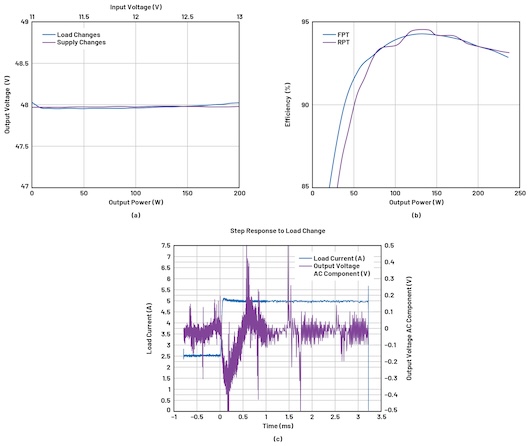
Figure 10. Resulting (a) output voltage regulation, (b) efficiency, and (c) 50% load-step response in RPT mode. Image used courtesy of Bodo’s Power Systems [PDF]
Dedicated Digital v. Micro Controllers for Power Conversion
Dedicated digital controllers for power conversion are a good alternative for the implementation of safe and reliable applications within the energy market. This is because, compared to microcontroller devices, they can assist an easier FS certification, which reduces the time to revenue of system-level designs. Because these devices are usually built for unidirectional power transfer, this paper explores their adaption to bidirectional operation. Theoretical models, simulations, and experimental studies demonstrate the application of an isolated bidirectional DC-to-DC converter for battery-based energy storage systems. The results validate the feasibility of the application, with similar performance achieved for both energy transfer directions.
This article originally appeared in Bodo’s Power Systems [PDF] magazine.
Related Content