Facebook
 Google
 GitHub
 Linkedin
Understanding the Design, Implementation, and Topologies of Integrated Magnetics
This article explores the design insights for integrated magnetics, implementation of components, and how integrated magnetics serve as a building block for power electronic converter topologies.
The increasing need for compact and effective power electronics systems has design engineers looking for innovative ways to design individual components as optimally as possible. In the previous article, Introduction to Integrated Magnetics, we covered the concept of integrating multiple magnetic components into a single structure to gain significant performance improvement. Read on to learn more about some design insights for integrated magnetics, implementation of components, and how integrated magnetics serve as a building block for power electronic converter topologies.
Design Insights for Building an Integrated Magnetic Structure
An integrated magnetic structure is formed by combining several magnetic components while maintaining the capability of performing multiple magnetic functions. There are two key concepts that need to be considered during the process of magnetic integration[1]:
- Core sharing
- Winding sharing
Core sharing is accomplished when distinct discrete integrated magnetic components are further integrated into a single component while retaining the number of turns of each winding and sharing the magnetic core.
Winding sharing is accomplished when a winding in the integrated magnetic structure contributes to the magnetization of more than one equivalent discrete magnetic component. Thus, copper and core savings can be evidenced along with a reduction in the copper losses.
Based on the power scaling law, the volume or weight of a magnetic device increases slower than its power handling capacity. This means that the power density is larger when the total power being processed is high. Thus, the use of a single, large power processing magnetic device is much better than using multiple smaller ones. A significant boost in power density can be realized by integrating several individual magnetic components.
Implementation: Components Used to Build an Integrated Magnetics Structure
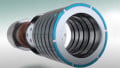
There are several types of integrated magnetics structures that are built and used in power electronics systems. The most basic one is a coupled inductor. When two inductors are wound on the same magnetic core, a coupled inductor is formed. It is very similar to a transformer but the magneto-motive forces (MMFs) of the windings are additive in nature. To understand a little more about the differences, take a look at Table I [2] where the characteristics of a coupled inductor are contrasted with that of a transformer.
Table I. Characteristics of Coupled Inductors and Transformers
| Characteristic | Coupled Inductor | Transformer |
| Air gap | Yes | No |
| Relative Magnetizing Inductance | Small | Large |
| Dependency of Magnetizing Inductance | Air gap | Core |
| Leakage Inductance Effects | Current waveform | Voltage waveform. |
| Desirable Leakage value | Large | Small |
| Magnetizing Current | Large | Small |
In the case of a coupled inductor, both the windings are driven by a voltage source simultaneously resulting in identical voltage waveforms driving the inductors. When multiple magnetic components are wound on the same core, like inductors and transformers, it turns out to be advantageous for certain topologies. This is possible when waveforms on the inductors and/or transformers are the same.
In the case of separate inductor windings, there is no flow of AC flux in the center branch while the DC fluxes add up. However, the air gap between the two windings has to be increased to maintain linear behavior.
Topologies that Use Integrated Magnetic Structures
Integrated magnetics structures form the building block of several key converter topologies that serve as critical systems for multiple applications. There have been a few topologies that are investigated with integrated magnetics like the boost converter, flyback, SEPIC, Ćuk converter, and its variants.
In the case of a conventional Ćuk converter, identical voltage waveforms appear across both inductors. Thus, the effective AC flux in the center branch is zero and can be removed. This yields a lighter, more compact magnetic component while maintaining the value of power density. Thus, there are no additional core losses which in turn leads to enhanced efficiency.
A variant of the Ćuk converter called coupled inductor Ćuk converter employs the integrated structure that comprises two or more inductances wound on the same core instead of employing individual inductances. This provides the ability to achieve a ripple-free terminal current either at the input side or at the output side based on the design along with significant performance improvement.
Another variant of the conventional Ćuk converter is one with a coupled inductor and isolation transformer. This is generally referred to as integrated magnetics Ćuk converter itself and its circuit is as shown in Figure 1. In this case, the core structure is chosen such that it can accommodate a minimum of four windings on it — a coupled inductor along with the primary and secondary transformers. This structure promises ripple-free input and output currents when designed appropriately along with enhanced electrical performance.

Figure 1. Circuit diagram of the Ćuk converter with integrated magnetics structure
Key References
- V. Valdivia et al. “Improving design of integrated magnetics for power electronics converters” in Electronics Letters 44.11 (2008), pp. 693–694.
- A. F. Witulski. “Introduction to modeling of transformers and coupled inductors” in IEEE Transactions on Power Electronics 10.3 (1995), pp. 349–357.
Related Content