Facebook
 Google
 GitHub
 Linkedin
Achieving High-Accuracy, Low Current Consumption With Current Sensors
Engineers designing high-efficiency power electronics systems need small current sensors that consume less power and measure high currents accurately.
Current measurement is one of the most common parameters used to evaluate, control, and diagnose the operating efficiency of electronic systems. Although current is a very common measurement, problems can arise when designers underestimate the nuances of several variables when measuring current. Top engineers use SiC MOSFET modules to design highly efficient inverters that meet the following design criteria. Current sensors also need to be designed with low operating power consumption and compact size, as these are the most important design criteria.
Current Sensors for Measurement
There are two main current measurement techniques: shunt resistors and the Hall effect.
Shunt resistors consume power as a result of the load current passing through the resistor, so the resistance value must be very low. Other important parameters of a current shunt resistor for measurement stability are TCR and thermal EMF. These two parameters can have a significant impact on current measurement accuracy. Current shunt resistors must operate over a wide current range. At low currents (such as in sleep or standby mode in battery applications), the thermal EMF of the shunt adds a measurable error voltage to the voltage produced by the current through the resistor. To minimize measurement error, this error voltage must be much lower than the minimum expected voltage produced by the associated current through the shunt resistor. The first step in measuring current flow is to convert the current into a more easily measured voltage parameter. A current shunt resistor is an inexpensive component that accomplishes this task. However, the value of the shunt resistor must be low to optimize the insulation technique and minimize its impact on the circuit and the power dissipation of the resistor itself. Solutions that use shunt resistors have different thermal aspects. The working principle of shunt current measurement is that the load current flows through the resistor, and the resulting voltage drop is measured. This results in power dissipation in the shunt resistor. Inverter designers must take care that the maximum shunt temperature does not exceed 200°C.
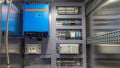
When using Hall-effect sensors, you must consider the maximum temperature of the busbar. Typical sensors are specified to operate below 85°C or below 105°C housing temperature, depending on the device used (Figure 1).
Power consumption test with current sensor-based module (Figure 1).

Figure 1. Temperature characteristics of a current sensor and power consumption measurement data. Image used courtesy of Bodo’s Power Systems [PDF]
Low-Power Hall-effect Sensors for Current Measurement
Typically, at certain power levels above 50 kW, shunting is not a viable option due to excessive power losses. Therefore, for high-power inverters, Hall effect sensors should be used around the output AC busbar. A schematic of this type of system is shown in Figure 1. This configuration provides a good solution for inverters with a simple interface to the controller and high electrical isolation properties. Because it uses the Hall effect to measure current, there is no power loss in the load current. There are two main types of Hall effect sensors: Open-loop and closed-loop current sensors. Open-loop sensors are less expensive, require less power supply, and have lower requirements, but they typically have error characteristics in terms of dynamic bandwidth, offset voltage, and drift over temperature. Closed-loop sensors overcome these error characteristics but are more expensive and have very high current consumption.
Table 2. Summary of key differences Four Approaches to Current measurement.
| Half Sensor Closed Loop (A) | Half Effect Sensor Open Loop (B) | NEW Hall Effect Sensor Closed Loop (C) | NEW Hall Effect Sensor Open Loop (D) | |
| Accuracy | high | medium | high | high |
| Cost | high | medium | high | medium |
| Physical Space required | very small | very small | very small | very small |
| Assembly/ Mounting Sensor | easy mounting, cable & plug connection | easy mounting, cable & plug connection | very easy mounting, cable & plug connection | very easy mounting, cable & plug connection |
| Withstand voltage | AC2000V, 1min | AC2000V, 1min | AC2000V, 1min | AC2000V, 1min |
| Step response time | typ. <1µs | typ. <3µs | typ. <1µs | typ. <3µs |
| Power supply | ±15V (20mA) | ±15V (25mA) | ±5V (18mA) | ±5V (15mA) |
In typical applications, open-loop Hall-effect sensors provide sufficient error characteristics. However, closed-loop Hall-effect sensors are used in very demanding applications where the highest control accuracy is required. The power supply requirements of closed-loop Hall-effect sensors are very high compared to other sensor types. A conventional cross-loop current sensor with a rated current of 100 A and a secondary output of 50 mA requires power consumption of 1 W when using an operating power supply of ±15 V. However, a cross-loop current sensor with a rated current of 100 A and a secondary output of 500 mV requires 0.5 W of power consumption when the operating power is +5 V. And an open-loop current sensor with 100 A and a secondary output of 500 mV requires only 0.1 W when the operating power is 5 V. Therefore, for a three-phase converter, the power supply must provide 3 W of power for a conventional closed-loop current sensor. However, the new open-loop type current sensor can improve power efficiency by 2.7 W compared to the existing ones when supplying total power of 0.3 W.
See Figure 1 and Table 2 for the technical differences between Hall-effect current sensor solutions.
J&D applies the latest AOCT technology inspired by DC metering design. We recently launched the IPCS series, which boasts the highest precision available. This innovative technology has been incorporated into J&D’s latest IPCS current sensor series, designed for non-intrusive and isolated measurement of DC, AC, and pulsed currents in the nominal range of 100 A to 800 A.
The IPCS sensors are one of the best options for top engineers: they meet high precision with low power consumption.
The IPCS sensors feature closed-loop and open-loop current sensors that enable high-precision, error-free measurements with a 5 V operating power supply. The technology is based on a zero-draft OPAMP IC that utilizes Hall effect technology in either closed-loop or open-loop mode. The technology offers excellent temperature characteristics from -40°C to +85°C and low offset drift, making it ideal for applications requiring high accuracy.
The sensors feature a solid-core type PCB mount design and a split core type panel mount or DIN rail mount type, and customers have the flexibility to select AC or DC currents from 5 A to 800 A. The IPCS current sensors are available in a variety of sizes.
IPCS current sensors are suitable for use in a wide range of applications, including modern string inverters that generate power on the AC side of 70-250 kW solar inverters, which by standard require very low DC components for output current. They are also ideal for DC billing meters, ESS, and EV charging modules (Figure 2).
Overall, J&D’s IPCS family of current sensors provides engineers with solutions to design efficient, lightweight, and compactly sized power modules while ensuring that they can deliver the highest levels of accuracy and precision in non-intrusive, isolated measurement of DC, AC, and pulsed currents.

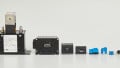
Figure 2. Conceptual diagram of EV charging module efficiency measurement. Image used courtesy of Bodo’s Power Systems [PDF]
DC Current Sensors for Side Metering
Cost-effective DC current sensors are used to measure DC current in industrial environments. Designed for accuracy and durability, the IDCS series products are ideal for providing precise current measurements in DC applications such as renewable energy or transportation (Figure 3).
The IDCS-I DC current sensor measures the DC load current of an electrical installation and transmits the information to a DC energy meter module on a cable connected to the sensor via RJ12. The family consists of solid-core and split-core sensors in various sizes ranging from 50 to 5000 A for use in new or existing electrical installations.
Benefits
- Plug and play
- Quick RJ12 connections allow for easy and reliable wiring.
- Sensor classes can be configured quickly.
- Flexible
- Solid-core and split-core DC current sensors from 50 to 5000 A, designed for new or existing electrical installations, are available in a variety of installation options.

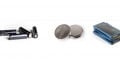
Figure 3. Power measurement diagram of a DC current sensor and DC meter for DC-side EV fast charging. Image used courtesy of Bodo’s Power Systems [PDF]
This article originally appeared in Bodo’s Power Systems [PDF] magazine
Featured image used courtesy of Adobe Stock