Facebook
 Google
 GitHub
 Linkedin
Distribution Transformers and Voltage Regulation—Part 2: Step-Down Transformers
Distribution transformers shape network voltage and fault behavior. Learn how winding configurations, vector groups, and grounding methods impact system performance and protection.
Distribution transformers sit at the heart of medium‑ and low‑voltage networks, stepping utility primary voltages down to utilization levels while shaping fault behavior, harmonics, and the practicalities of protection.
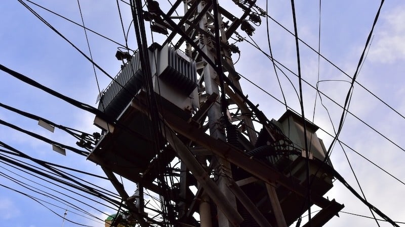
Figure 1. Step-down transformer on an electricity transmission tower. Images used courtesy of Adobe Stock (licensed).
Beyond kVA and efficiency ratings, winding connections, vector groups, and grounding choices determine phase relationships, zero‑sequence paths, and the feasibility of parallel operation. This article examines the operating principles and the connection decisions that most strongly affect voltage regulation and system performance.
Step‑Down Transformer Operating Principle
A distribution transformer transfers energy by electromagnetic induction: time‑varying flux links primary and secondary windings on a common core, inducing voltages proportional to turns. For an ideal transformer, the fundamental relationships are given by the turns ratio and power balance:
$$\text{Voltage ratio: } \frac{V_p}{V_s} = \frac{N_p}{N_s}$$
$$\text{Current ratio: } \frac{I_p}{I_s} = \frac{N_s}{N_p}$$
$$\text{For the ideal case: } P_{in}= P_{out}$$
These equations follow from Faraday’s law and equal flux linkage in both windings.
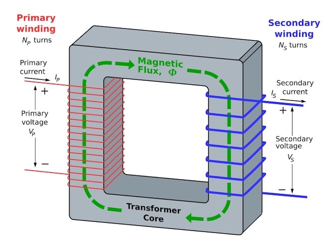
Figure 2. Step down transformer operating mechanism. Image used courtesy of Wikipedia.
In system studies, per‑unit representation simplifies comparisons across voltage levels and nameplate ratings. The per‑unit value of any quantity is defined as the actual value divided by a selected base value:
$$X_{pu} = \frac{X_{actual}}{X_{base}}$$
Selecting base MVA and base kV sets base current and base impedance, allowing impedances to be combined and compared without repeated ratio conversions across transformers. This normalization is foundational for short‑circuit and voltage‑drop analysis in distribution feeders.
Voltage regulation at the service point is shaped by transformer leakage impedance and tap position. In practice, voltage drop under load can be estimated in per unit by combining the feeder and transformer series impedances and applying the expected load power factor; on‑load tap changers or de‑energized taps then adjust the no-load ratio to bring secondary voltage into tolerance. IEC 60076‑1 identifies connection symbols, rated quantities, and application information relevant to specifying taps and parallel service.
Common Winding Configurations
Delta–Wye (Δ–Y): A widely used distribution connection that provides a grounded neutral on the wye side for 4‑wire secondary service. The delta winding offers a local path for triplen (3rd, 9th, 15th, …) harmonic magnetizing currents, limiting their appearance on the line side and aiding voltage waveform quality. The configuration introduces a 30 degree phase displacement between primary and secondary phasors.
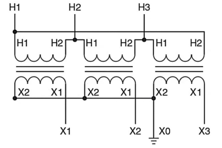
Figure 3. Delta-Wye connection diagram. Image used courtesy of Ahmed Sheikh.
Wye–Wye (Y–Y): Attractive for ratio flexibility and insulation economy, but an ungrounded Y–Y arrangement can suffer neutral instability and third‑harmonic voltage distortion because triplen components have no internal circulating path. A delta tertiary or solidly grounded neutral is commonly applied to stabilize the zero‑sequence network and control harmonic voltages.
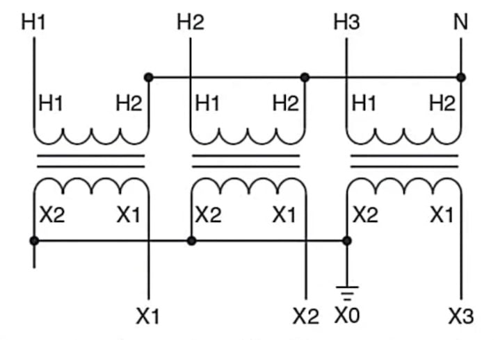
Figure 4. Wye-Wye connection diagram. Image used courtesy of Ahmed Sheikh.
Delta–Delta (Δ–Δ): Robust under unbalanced loading and tolerant of a single unit failure in a bank. With no neutral available, separate grounding measures are required for 4‑wire loads. The closed delta inherently traps triplen harmonics, confining them to the delta loop and reducing their propagation upstream.
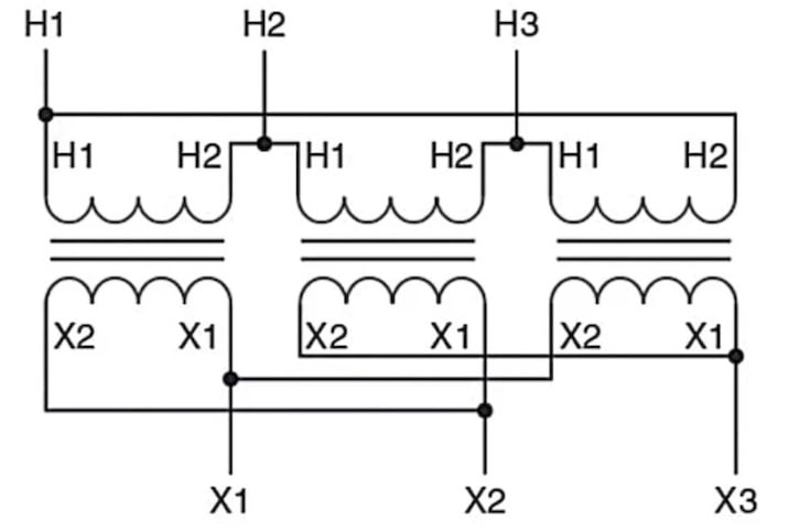
Figure 5. Delta-Delta Connection Diagram. Image used courtesy of Ahmed Sheikh.
Vector Groups and Phase Shift
Vector groups provide a compact, standardized description of winding connections and the phase displacement between high‑ and low‑voltage windings. IEC 60076‑1 defines the notation and the “clock number” method: capital letters denote the high‑voltage side, lowercase the low‑voltage side, and the numeral (0–11) indicates the low‑voltage phasor position in 30 degree steps relative to the high‑voltage phasor oriented at 12 o’clock. For example, Dyn11 indicates a delta‑connected HV, wye‑connected LV with neutral brought out, and a 30 degree displacement corresponding to “11 o’clock.”
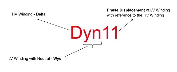
Figure 6. In this example, Dyn11 represents a delta‑connected HV, wye‑connected LV with neutral brought out, and a 30 degree displacement corresponding to “11 o’clock.” Image used courtesy of Ahmed Sheikh.
The 30 degree displacement has direct operational implications. Protective device settings that reference phase angle—such as directional elements, differential relays, or synch‑check interlocks—must account for the vector group so that measured quantities align correctly. Similarly, instrument transformer burdens and wiring are arranged to match the connection’s inherent shift.
When feeders or secondary buses are paralleled, mismatched clock numbers cause circulating currents and immediate protection trips even when ratios match at no load; therefore, the vector group must be identical for sources intended to operate in parallel.
Parallel operation also depends on more than the connection symbol. To share load without excessive circulating current, units must have compatible nominal ratios (and tap positions), closely matched percentage impedances and X/R ratios, and the same phase sequence and polarity. IEC 60076‑1 addresses parallel operation in specification data, and industry practice documents emphasize matching vector group, ratio, and impedance before attempting to close parallels. Where regulated transformers are paralleled, specialized schemes are used to coordinate tap movement and suppress circulating reactive power.
Grounding and Neutral Considerations
The grounding method determines zero‑sequence behavior, fault magnitude, and the sensitivity and selectivity of protection.
- Solidly grounded systems tie the neutral directly to earth, providing a low‑impedance path for ground faults. Single line‑to‑ground fault currents can approach or exceed three‑phase fault magnitudes at distribution voltages, enabling fast, sensitive protection but placing higher thermal and mechanical duty on equipment and requiring careful coordination of ground‑fault elements. IEEE grounding practice document (IEEE Std 80) discusses these characteristics and when solid grounding is preferred.
- Resistance‑grounded systems insert an intentional resistor between the transformer neutral and earth. Low‑resistance grounding (LRG) limits fault current to hundreds of amperes, supporting selective feeder protection while reducing damage energy. High‑resistance grounding (HRG) limits fault current to a few amperes, allowing continued operation on a single ground fault while alarm and location processes proceed; it is applied where service continuity outweighs immediate tripping. Selection among solid, LRG, and HRG considers process criticality, arc‑flash energy, and ground‑fault detection requirements.
Grounding choice intersects directly with winding configuration and vector group:
- Delta–Wye with a grounded wye secondary provides a defined neutral reference for 4‑wire distribution and an internal path for triplen harmonics in the delta. This pairing stabilizes the neutral voltage and contains triplen currents, benefits that contribute to its prevalence in commercial and utility networks.
- Wye–Wye without a delta tertiary can exhibit neutral shift under unbalanced or harmonic conditions because zero‑sequence currents have no internal circulation path. Adding a delta tertiary or grounding the neutral establishes a zero‑sequence route, reducing third‑harmonic voltage distortion and making protective relaying more predictable.
- Delta–Delta has no neutral; grounding is provided by a separate grounding transformer (zig‑zag or wye‑delta) if 4‑wire loads or ground‑fault protection sensitivity demand it. The delta’s ability to trap triplen components is useful when serving nonlinear loads that would otherwise elevate neutral currents and distort line‑to‑neutral voltages.
These zero‑sequence behaviors influence fault studies. With a grounded‑wye secondary, line‑to‑ground faults on the low‑voltage side see a complete zero‑sequence loop and thus higher magnitudes; in contrast, a delta on the source side prevents zero‑sequence currents from passing upstream. Accurately modeling this requires representing sequence networks and the transformer’s connection per its vector group, then solving in per unit so that feeder, transformer, and source impedances are consistently combined.
Protection schemes align with the grounding method:
- On solidly grounded systems, ground‑fault relays typically employ sensitive pickup and directional elements to maintain selectivity on interconnected feeders. High zero‑sequence fault levels permit fast clearing to mitigate equipment stress.
- On LRG systems, feeder ground‑fault relays are set above the resistor’s let‑through current; sensitivity remains good, but coordination margins improve relative to solid grounding.
- On HRG systems, ground‑fault detection uses sensitive voltage and current relays measuring neutral‑to‑ground voltage rise and the limited neutral current through the resistor; tripping is usually reserved for the second ground fault on a different phase, when the network behaves as a line‑to‑line fault through ground.
A Combination of Factors
Distribution transformers play a critical role in shaping voltage profiles and system behavior across medium- and low-voltage networks. Electromagnetic principles and the turns‑ratio equations define the baseline relationships between V, I, and N, but system behavior depends on winding connections, vector group phase displacement, and how the neutral is treated.
Delta windings provide a local path for triplen components; grounded wye windings create a reliable reference and a zero‑sequence path; and Y–Y arrangements benefit from a delta tertiary or intentional grounding to stabilize the neutral. Parallel operation becomes practical only when vector groups, ratios, impedances, and taps align. Throughout, per‑unit modeling provides a common scale to evaluate regulation, sharing, and faults across voltage levels.
With IEC 60076‑1 guiding connection symbols and data, and IEEE Std 80 shaping grounding and protection, transformer configurations can be selected to achieve stable voltage, manageable fault currents, and reliable protection in modern distribution systems.