Facebook
 Google
 GitHub
 Linkedin
Substation Commissioning and Testing—Part 2: Pre-Commissioning Inspections
This article walks through pre‑commissioning inspections and electrical tests commonly used in utility and industrial substations, translating standards into actionable steps and decision points for engineering teams.
Commissioning a substation is far more than a procedural energization. It is a structured technical process designed to verify that equipment was installed as intended, that interconnections are correct, and that insulation, grounding, and control systems will perform safely under both normal and fault conditions.
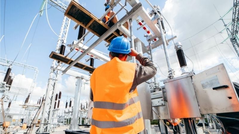
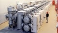
Inspecting a substation. Image used courtesy of Adobe Stock
Pre‑Commissioning Inspections
Thorough inspections catch many issues before connecting instruments and applying voltages. They also provide context for interpreting electrical test data later.
Visual and Mechanical Inspections
Verification against design: Confirm that equipment ratings, nameplates, and terminal designations line up with single‑line diagrams, general arrangement drawings, and vendor schematics. Where acceptance test specifications are part of the project (such as ANSI/NETA ATS), use them to frame the inspection scope and documentation.
Bolted joint integrity: Inspect and torque bus joints, pad connections, and terminal hardware per manufacturer values or project torque tables. Record any rework and mark joints as verified. Elevated resistance at one joint compared with peers often indicates insufficient torque or surface preparation and should be addressed before electrical testing.
Mechanisms and alignments: Check disconnect blade alignment, breaker mechanism travel, and drive linkages through local and remote operations if available. Misalignment here frequently shows up later as abnormal timing or contact wear during acceptance tests.
Fluids and gas systems: Verify transformer oil levels; for gas‑insulated apparatus, verify SF₆ gas density/pressure alarms, density switches, and moisture indicators. Acceptance of gas quality and handling procedures should follow the applicable IEC standards: new SF₆ quality (IEC 60376), re‑use and by‑products (IEC 60480), and handling for HV equipment (IEC 62271‑4).
Grounding and Bonding Verification
Grid continuity: Perform continuity/integrity checks between key ground points (such as transformer neutrals, risers, yard structures) using a controlled current source and four‑wire measurement to mitigate lead/contact resistance errors. Modern practice uses 100-300 A injection with separate sense leads, documenting voltage drop and inferred resistance path by path. This approach aligns with practices described in IEEE Std 80 and IEEE Std 81.
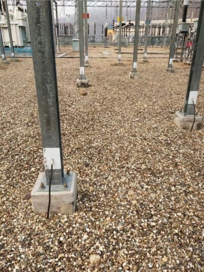
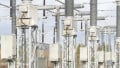
Figure 1. Grounding grid underneath the substation. Image used courtesy of International Electric Testing Association
Bonding: Confirm bonding of structures, fences, gates, equipment frames, cable trays, and metallic raceways. Non‑obvious bonds such as lighting poles, camera masts, and remote I/O cabinets should be included in the continuity route list.
CT/VT secondary and control circuit grounding: Verify each instrument transformer secondary has a single, intentional ground point and that secondary cases are bonded appropriately. Use the latest guidance in IEEE C57.13.3 for grounding practices and C57.13 for markings and polarity.
Wiring and Interconnection Checks
Point‑to‑point verification: Match every field wire to its schematic destination, including inter-panel and yard terminations. Tag deviations or field changes with redlines.
CT and VT polarity/continuity: Confirm polarity (H1/X1) orientation and secondary continuity before energization to avoid misoperations, especially for differential, directionality, and synch‑check functions. IEEE C57.13 describes polarity and terminal-marking conventions that should be visible and consistent with the drawings.
Terminal labeling and cable ID: Confirm consistent labeling through terminations per project standards and codes. For mixed voltage systems in a control building, ensure identification and documentation comply with NEC 210.5 and related labeling practices.
Separation of AC, DC, and communications: Maintain physical segregation and shielding per design to minimize induced noise and improve immunity. When in doubt, reference applicable code practices for identification and separation in enclosures and raceways.
Electrical Pre‑Commissioning Tests
With mechanical and wiring checks complete, proceed to electrical tests to validate insulation systems, magnetics, and current‑carrying paths.
Insulation Resistance (IR) Testing
IR testing establishes baseline insulation health and detects workmanship issues such as contamination, moisture, or damage.
Purpose and interpretation: The measured resistance reflects leakage and absorption currents in the insulation system. Polarization Index (PI), the ratio of 10‑minute to 1‑minute readings, provides additional insight into dryness and cleanliness for many windings. IEEE 43 explains when PI is meaningful and notes that if the one‑minute IR exceeds about 5,000 MΩ, PI may not be a reliable indicator due to measurement sensitivities.
Test voltages: Typical field practice uses 500 VDC for 300 V control wiring and 1 kVDC for 600 V wiring. Higher DC voltages are selected for MV/HV apparatus per manufacturer data or project acceptance specs (such as ANSI/NETA ATS tables) to avoid overstressing solid‑state devices. Isolate electronics before applying DC tests to auxiliary/control circuits.
Temperature correction and PI: Temperature significantly affects IR. Readings are commonly normalized to 40°C for trending. IEEE 43 describes how to treat PI with respect to temperature and cautions about performing the test above the dew point to avoid moisture‑related artifacts.
Acceptance and trending: Many organizations rely less on absolute acceptance numbers and more on comparison to manufacturer recommendations and consistency with prior records. Using ANSI/NETA ATS as a framework ensures results are recorded in a way that supports future maintenance trending across outages.
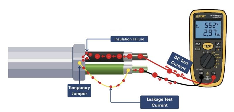
Figure 2. Insulation resistance testing. Image used courtesy of AEMC Instruments
Transformer Tests
Transformer testing follows a structured sequence: visual checks, IR, winding resistance, ratio/vector group verification, excitation, oil diagnostics (where applicable), and dielectric tests as specified.
Winding resistance: Measure the DC resistance of each winding at a stable temperature, and, where possible, correct the results to a common reference temperature. Compare resistance values between phases of the same winding and tap position (for example, HV phase-to-phase at the nominal tap). Significant differences can indicate loose connections, tap-changer contact problems, or shorted turns. Field practice typically requires agreement within approximately 1% among corresponding windings, with any outliers investigated.
Turns ratio (TTR) and vector group: Verify ratio at all taps and confirm phase relation (clock position). A common field acceptance limit is ±0.5% from the nameplate/calculated ratio or adjacent coils. Any deviation beyond this threshold typically triggers deeper investigation (connections, taps, or instrument setup). ANSI/NETA ATS—used widely for acceptance—documents this criterion.
Excitation current and magnetizing behavior: Measure no‑load (excitation) current while recording applied voltage and frequency. IEEE C57.12.90 details how excitation current is determined in conjunction with no‑load loss testing and how results are expressed as a percentage of rated line current.
Engineers commonly observe that, in three-leg core transformers, two phases draw similar excitation current while the third draws a lower value due to core flux paths. Significant deviation from this expected pattern may indicate core or winding issues or an incorrect test setup.
Oil sampling and dielectric strength (liquid‑filled units): Draw representative samples with clean techniques and test dielectric breakdown using accepted methods—ASTM D1816 (VDE electrodes) for sensitivity to dissolved moisture and IEC 60156 for general acceptance and monitoring. Note that a high breakdown voltage alone does not prove the absence of contaminants; it only indicates that contaminant levels are not large enough to reduce the breakdown voltage under the specified test conditions. Standards define these conditions and guide interpreting results in the presence of moisture and other contaminants.
When dielectric and chemical results fall outside specification, investigate dehydration/degassing, filtration, or oil replacement per transformer and fluid standards (and manufacturer instructions) before energization.
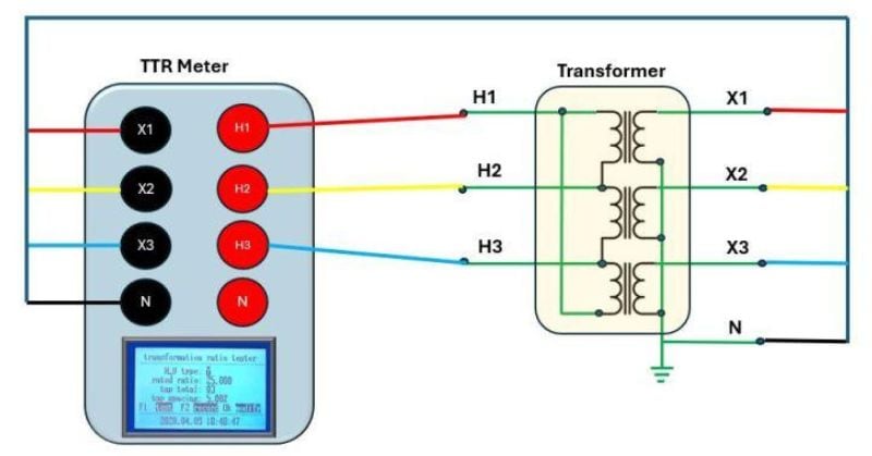
Figure 3. Transformer turns ratio test. Image used courtesy of Power Transformer Health
Switchgear and Buswork Tests
Switchgear, bus systems, and connections determine the reliability of current‑carrying paths and the assembly's dielectric integrity.
Contact resistance testing: For HV circuit breakers and bus joints, measure main path resistance using a four‑terminal method at sufficient test current to overcome contact film effects. IEC 62271‑100 routine test guidance requires the measured resistance not exceed 1.2 × Ru (the resistance measured before the type‑test temperature‑rise), a practical acceptance approach when manufacturer targets aren’t provided.
Insulation checks: Perform phase‑to‑phase and phase‑to‑ground insulation resistance and, where specified, power‑frequency dielectric withstand tests. For auxiliary and control circuits, IEC 62271‑100 specifies 1 kV or 2 kV for 1 second; always isolate sensitive electronics before testing.
Bus phasing and continuity: Confirm phase sequence (A‑B‑C) and rotation using approved methods before any tie or backfeed is attempted. Modern commissioning practice includes phasing of busbars, VT secondary checks, and alignment with existing yard systems and auxiliaries to avoid incorrect rotation and protection misoperations. Supplemental guidance from utility standards emphasizes phasing checks across busbars, auxiliary transformers, and voltage transformers.
Ground grid continuity at switchgear: Extend the ground continuity program into indoor switchboards and GIS enclosures, verifying connections to the station grid with low-ohm injection and appropriate sense leads, consistent with IEEE 80/81 grounding test methods.
Conclusion
Effective substation commissioning blends methodical inspection with targeted electrical testing, carried out under a clear framework of standards and project specifications. Visual and mechanical checks ensure equipment is installed as designed and ready for energization. Grounding verification and wiring checks eliminate common defects that can compromise safety and reliability. IR testing, transformer diagnostics, and switchgear/buswork measurements then establish the electrical integrity of the installation.
Throughout, adherence to recognized standards—IEEE 80 for grounding, IEEE 43 for IR testing principles, IEEE C57.12.90 and C57.13 for transformer testing and instrument transformer fundamentals, IEC 62271‑100 for HV switchgear, and ANSI/NETA ATS for field acceptance test structure—provides a robust technical basis for decisions and establishes a usable baseline for future maintenance. When executed effectively, commissioning converts a build into an operational asset that meets safety margins, protection performance, and long-term reliability requirements.