Facebook
 Google
 GitHub
 Linkedin
Pulsiv Unveils Its Own Nomogram, a Graphical Tool for DCM Flyback Designs
With this new tool, engineers can quickly and accurately identify primary side inductance and minimum duty cycle—without complex equation-based methods.
Power system design requires intricate and precise engineering, where every calculation can significantly impact efficiency and performance. These calculations involve a myriad of variables, from inductance and duty cycle to peak current.
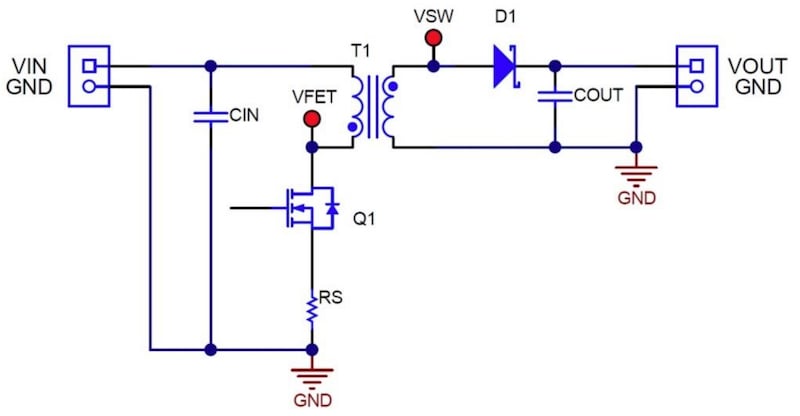
This simplified flyback converter can operate in DCM. Image used courtesy of Texas Instruments (Downloads as a PDF)
To make this process simpler and more intuitive, Pulsiv announced a nomogram for discontinuous conduction mode (DCM) flyback designs. A nomogram is a visual calculating device that depicts the graphical computation of a function. It generally transforms complex mathematical equations into simple, two-dimensional visual diagrams that can be used for calculations.
Pulsiv released its own nomogram as an alternative to equation-based methods, allowing designers to quickly and accurately pinpoint primary side inductance and minimum duty cycle.
A Nomogram for DCM Flyback Converters
Pulsiv's nomogram targets DCM flyback converters, a type of switching power supply that is simple, low-cost, and flexible in various applications. However, optimizing these converters for efficiency across varying power levels and load conditions can be complex, involving intricate calculations to determine the right balance of components and configurations. Pulsiv's nomogram addresses this challenge with a visual tool that makes these calculations faster and less error-prone.
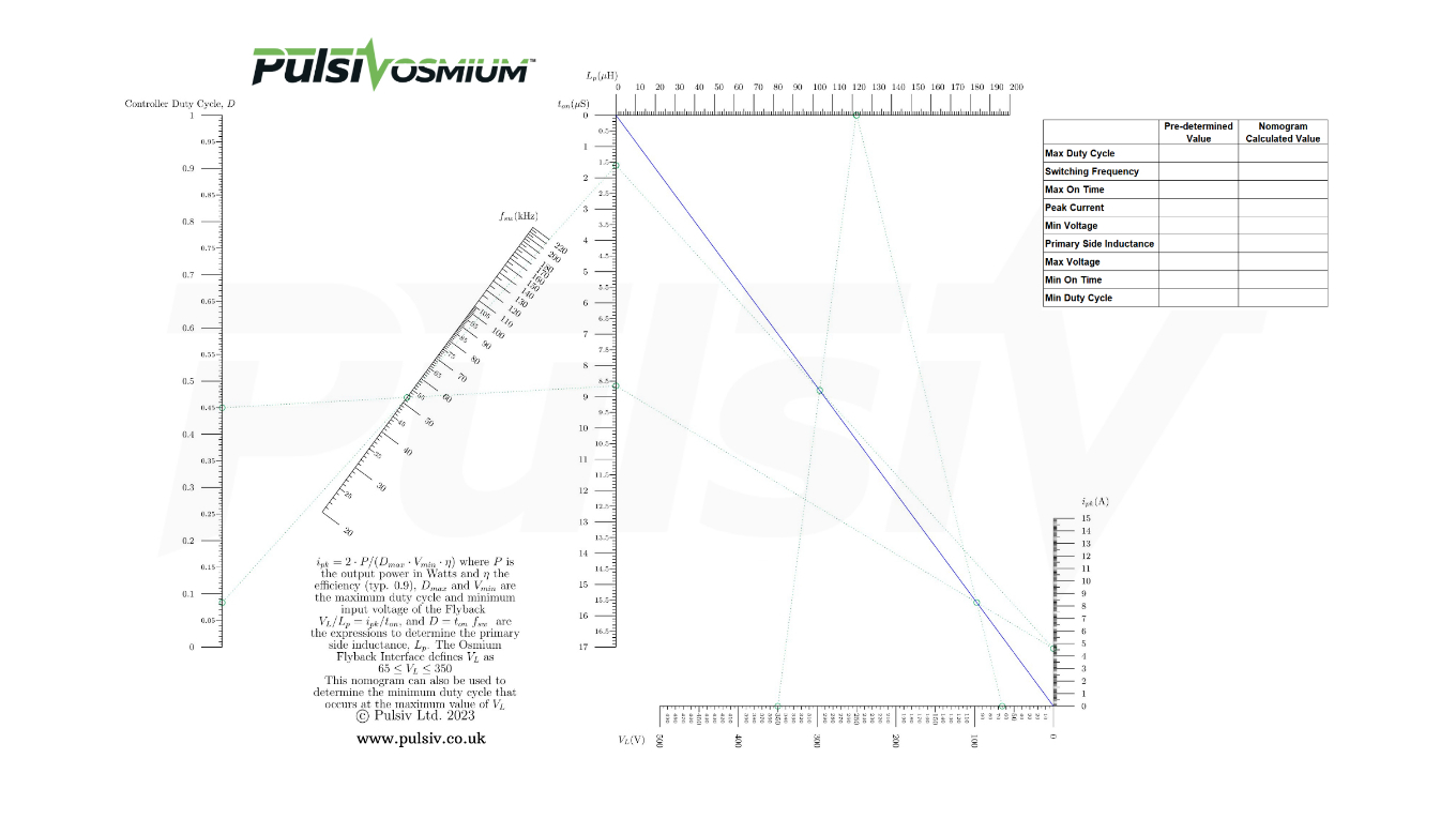
Pulsiv’s DCM nomogram. Image used courtesy of Pulsiv (Click to enlarge.)
The nomogram encapsulates complex relationships between multiple variables—such as inductance, duty cycle, and peak current—into a user-friendly, graphical format. With it, engineers can determine the optimal values for these parameters with a simple ruler, drawing a line across the relevant scales to find the intersection points that yield the desired results.
According to Pulsiv, the tool is particularly valuable when designing high-efficiency systems that operate over a wide range of conditions. By using the nomogram, engineers can quickly adjust design parameters to maximize efficiency, which is crucial for reducing energy consumption and heat generation in electronic systems.
The Purpose of Nomograms in Engineering
In nomograms, the position of a point in two dimensions can represent a number. By aligning scales for different variables on a plane, a user can solve equations by drawing a line through the corresponding points on these scales. The intersection with another scale shows the result. This method can be especially powerful when dealing with equations that would be cumbersome to rearrange or solve algebraically.
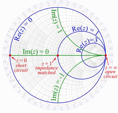
A Smith Chart is a popular nomogram in electrical engineering. Image used courtesy of Digi-Key
In electrical engineering, nomograms are particularly useful for visualizing the relationships between different electrical parameters. For instance, in power electronics, a nomogram can graphically represent the relationship between voltage, current, resistance, and power, providing a quick reference for circuit design and analysis without complex calculations. One popular example of nomograms in electrical engineering is the Smith Chart, which calculates impedance matching in RF systems.
A New Way to Calculate
Pulsiv's nomogram may be a practical upgrade to power system designers' toolkit. By simplifying the process of calculating key parameters for DCM flyback converters, the tool can streamline design cycles and potentially improve the performance of power systems. While the nomogram is an incremental improvement, it acknowledges the complexity of power system calculations and offers a method to better manage that complexity.