Facebook
 Google
 GitHub
 Linkedin
What Is an Inductor?
Learn more about Faraday’s law of induction.
An inductor is a circuit element governed by Faraday’s law of induction:
\(\varepsilon=-\frac{d\Phi}{dt}\) [1]
where ε is electromotive force and Φ is the magnetic flux threading a conductive loop. The negative sign indicates that the electromotive force opposes the direction of the current flow that created the flux.
The property of self-inductance indicates the strength of the flux field associated with an inductor and electromagnetic flux is directly proportional to current flow, so Faraday’s law for an inductor can be written as:
\(\varepsilon=-L\frac{di}{dt}\)
[2]
where L is self-inductance and di/dt is the time rate of change in current flow.
Basic electrical equations have a mechanical analogy. Electromotive force is analogous to mechanical force. Current is the velocity of charge. Therefore di/dt is the rate of change of the velocity of charge, which is acceleration. Inductance represents inertia to a change in current, or the electrical equivalent of mass, so equation 2 is the electrical equivalent of Newton’s second law of motion:
\[F=ma\]
Further, in the mechanical analogy, a capacitor is the equivalent of a mechanical spring and a resistor is the mechanical equivalent of friction. The equations describing the behavior of an electrical circuit consisting of these basic circuit elements are identical in form to the equations describing a basic mechanical system consisting of mass, springs, and friction. Like a mass stores the work done on it as kinetic energy, an inductor stores energy in its field. The stored energy will be recovered when the field collapses.
The units of inductance are volts-seconds per amp. A unit of one volt-second per amp is known as a Henry in honor of Joseph Henry the American scientist who independently worked on electromagnetic induction while Michael Faraday was also experimenting and developing his theories in England.
Calculating Inductance
Equation [1] describes the induced voltage in a single turn loop subjected to a changing magnetic field. A multi-turn coil is just an assembly of individual loops in series, so the induced voltages add and Faraday’s law becomes:
\(\varepsilon=-\frac{Nd\Phi}{dt}\) where N is the number of turns in the coil.
[3]
Combining equations [2] and [3] gives:
L\(\frac{di}{dt}=N\frac{d\Phi}{dt}\)
Or in integral form,
\(L=\frac{N\Phi}{i}\)
[4]
But Φ is the integral of the magnetic field B over the cross-sectional area of the coil. For a uniform cylindrical coil neglecting end effects and assuming the relative permeability of the core material to be constant, B can be approximated as:
\(B=\mu_{r}\mu_{0}NiA/1\) [5]
where μr is the relative permeability of the core material, μ0 is the permeability of free space, A is the cross-sectional area of the coil, and l is its length.
Substituting equation [5] in [4] yields a formula for approximating the inductance of a cylindrical coil with a linear core material (constant μr):
\(L=\frac{\mu_{o}\mu_{r}N^{2}A}{l}\)
[6]
Equation [6] says that in designing an inductor, the only variables that determine the value of the inductor are the number of turns, the physical size of the coil, and the relative permeability of the core material.
Applications
The principle of electromagnetic induction is exploited throughout electrical engineering in the form of motors, generators, transformers, solenoids, transducers, relays, and the inductor as a circuit element. The inductor is used in AC circuits from power line frequencies to RF to suppress electromagnetic interference, limit in-rush currents, cancel capacitive reactance in impedance matching, form a tuned resonant circuit with capacitors, and in discrete component ladder filter structures that implement a low-pass, high-pass, bandpass, or band notch frequency response.
If the flow of current through an inductor is suddenly interrupted, for example, by opening a switch, the di/dt of equation [2] is very large and the collapsing field of the inductor creates a large voltage across it, potentially arcing across the switch contacts and dissipating the stored energy in the field as heat in the electrical arc. This principle is exploited in spark-ignition engine ignition coils to fire the spark plug.
Transient Analysis
Transient analysis involves solving the differential equation (Equation [2]) for the voltage across the inductor. The solution is shown below for a simple circuit with a DC supply and the switch closed at time zero. An ideal inductor will look like an open circuit in response to a voltage step function and it will look like a short circuit in a steady-state DC circuit. These two principles define boundary conditions.
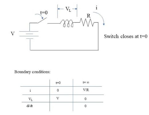
\(V_{L}=\frac{Ldi}{dt}\)
[7]
A solution to the differential equation is:
\(i=\frac{V}{R}-\frac{V}{R}e^{-\frac{Rt}{L}}\)
[8]
So,
\(\frac{di}{dt}=\frac{V}{L}e^{-\frac{Rt}{L}}\)
[9]
Substituting [9] in [7] gives:
\(V_{L}=Ve^{-\frac{Rt}{L}}\)
[10]
To verify the above equations satisfy the boundary conditions, we have from [8] at t=0, i = 0, and at t = ∞, i = V/R; from [10], at t = 0, VL = V, and at t = ∞, VL = 0; and from [9] at t = ∞, di/dt = 0.
Steady-State Analysis
Under steady-state sinusoidal excitation, the current through an inductor lags the voltage across it by 90 degrees, as is apparent from Equation [2]. The maximum rate of change of current (di/dt) occurs when the sinusoidal current is passing through zero, and its minimum, which is zero, occurs when the current is cresting (Figure 1).
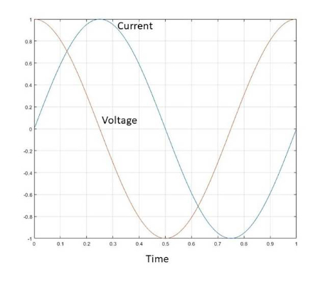
Figure 1. Voltage across and current through an ideal inductor in a steady-state sinusoidally excited AC circuit. Image used courtesy of Blaine Geddes
In a steady-state sinusoidal AC circuit, the inductor has an impedance of:
\(X_{L}=j\omega L\), where ω is angular frequency in radians per second and \(j\,is\sqrt{-1}\) indicating the impedance is reactive and inverse to that of a capacitor.
In analyzing steady-state sinusoidal AC circuits, a phasor representation is often used, where complex voltages, currents, and impedance are represented in polar form as a magnitude and phase angle, which makes multiplications and divisions easier, but a summation requires conversion to rectangular form. Figure 2 shows an example of a simple circuit.
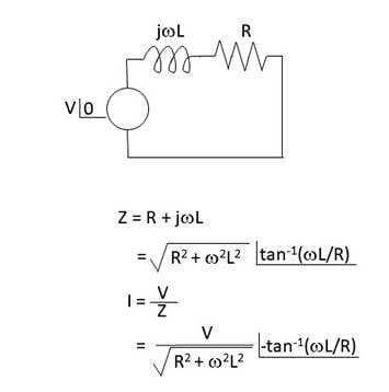
Figure 2. Calculating current flow in a simple circuit with steady-state sinusoidal AC excitation. Image used courtesy of Blaine Geddes
Inductors in Series and Parallel
As with resistors, the total impedance of inductors connected in series is simply the sum of the individual impedances. Therefore the total equivalent inductance is simply the sum of the individual inductances.
For inductances connected in parallel, the effect is also analogous to resistors in parallel. The admittances add to produce a total admittance that is the sum of the individual admittances.
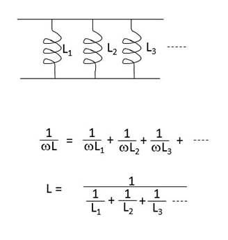
Figure 3. Inductors in parallel. Image used courtesy of Blaine Geddes
Inductor Core Materials for Power Line Frequencies
Ferromagnetic materials can be broadly classified as either hard or soft. Hard ferromagnetic materials have a high magnetic remanence and a high coercive field, making them suitable for use as permanent magnets. Soft ferromagnetic materials are the opposite. They have low coercive fields and magnetic remanence, making them suitable for use in alternating fields. Inductor and transformer core materials for AC fields are soft materials.
For inductors used at power line frequencies and frequencies extending into the low-kiloHertz range, the most common core material is a steel alloy known as electrical steel or transformer steel. The steels are sold as thin sheet stock. The sheets are punch sheared to shape by the component manufacturer and laminated to form the magnetic core. The laminations are coated to minimize inter-sheet electrical conductivity. The three grades of steel for magnetic use in order of increasing cost are low-carbon steel, non-oriented silicon steel, and grain-oriented silicon steel. All electrical steel is manufactured to close metallurgical tolerances with very low impurity levels, so they are all relatively high-cost steels.
Electrical steels have very low carbon contents, usually less than 0.08%. Manganese is usually added. Sometimes other alloying elements such as phosphorus are added to improve punching properties. Low carbon steel is the least expensive option of magnetic steel, but it will have the highest eddy current losses.
Silicon is one of steel’s most economical alloying elements to increase resistivity. Increased resistivity of magnetic steel will mean reduced eddy current losses under alternating current magnetization. The loss parameter for electrical steel can be reduced to a single number of Watts per unit mass when tested to a specific ASTM standard. ASTM A677-16 specifies a standard for non-oriented electrical steels. A typical composition of a silicon electrical steel is 2.80-3.50% Si, 1.40 – 1.60% Al, 0.05-0.10% Mn, 0.03-0.05% C, < 0.040% P, < 0.003% S.
Grain-oriented electrical steel offers the lowest loss but at the highest cost. The grains are oriented through a cold rolling process. The oriented grains will mostly have a similar crystallographic orientation which is preferential for magnetic flux orientation; hence the induced magnetic field will be mostly in the plane of the sheet, thus reducing eddy current losses.
Inductor Core Materials for Higher Frequencies
For higher frequency applications, ferromagnetic cores are commonly ferrite. Ferrite is a soft ferromagnetic ceramic compound consisting mainly of ferric oxide and containing other metal oxides, such as manganese, zinc, and nickel oxides. Being ceramics, ferrites have much higher resistivities than metals. Therefore they have lower hysteresis losses, which becomes a significant advantage at higher frequencies. Nickel ferrites maintain their permeability over a wider range than manganese and zinc ferrites and offer lower losses at higher frequencies. Still, manganese and zinc ferrites have a higher permeability at lower frequencies and saturate at higher flux densities than nickel ferrites.
Small signal high-frequency inductors are available as chip inductors for PCB mount. They are typically wire-wound inductors on a ceramic core. Parasitic capacitive effects become more significant as the operating frequency rises. Some parasitic shunt capacitance of the windings and the package will form a resonant tank circuit such that the impedance deviates from ideal and exhibits a peak at some frequency beyond which capacitive effects dominate. At some frequency, the inductor effectively becomes a capacitor. Figure 3 shows a typical performance curve over frequency for a small signal chip inductor.
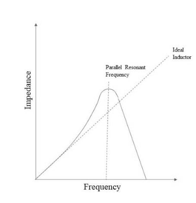
Figure 4. Representative inductor performance versus frequency. Image used courtesy of Blaine Geddes