Facebook
 Google
 GitHub
 Linkedin
ANPC Converter Design for Efficient Energy Storage Systems
A doubling of new energy storage installations globally has driven a change in power converter design for utility-scale systems. With an appropriate design, semiconductor efficiencies above 99% can be achieved.
This article is published by EEPower as part of an exclusive digital content partnership with Bodo’s Power Systems.
Without sufficient storage, switching to renewable energy will not be sustainable. Therefore, Battery Energy Storage Systems (BESS) are a true growth opportunity. A doubling of new energy storage installations globally from 2022 to 2023 has driven a change in the approach to power converter design for utility-scale systems. With an appropriate design, semiconductor efficiencies above 99% can be achieved.
The ongoing shift to renewable energy sources requires energy storage to ensure a continuous and reliable supply of energy to the grid. Massive growth in BESS installations has been driven by government-mandated renewables projects where energy storage systems must be co-located with generation. Additionally, advances in battery technology have increased the power density of BESS containers, making installations feasible in areas with limited footprints.
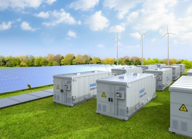
Image used courtesy of Adobe Stock
The potential for BESS to provide grid stability is yet to be fully exploited. They can provide peak shaving, load shifting, and backup power through integration into applications such as data centers. These applications have so much growth potential that the International Energy Agency predicts a growth in the cumulative global installations of utility-scale batteries from 54 GW in 2023 to more than 500 GW in 2030.
BESS Design
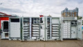
Utility-scale, AC-coupled BESS have traditionally relied on the same central inverter approach as solar, where a single inverter was fed from a bank of batteries (Figure 1). The power conversion system (PCS) consisted of an MW-scale, bi-directional 2-level (1000 V) or 3-level (1500 V) voltage source inverter. This system, packaged in a 20-foot container, was considered cost-effective as it used existing inverter designs from already developed (and co-deployed) solar equipment. However, experience has shown that this configuration can cause serviceability challenges, as a single failure in the inverter would render the entire system unusable. Furthermore, the increasing diversity of BESS installation locations means that more granularity is required for battery bank sizes.
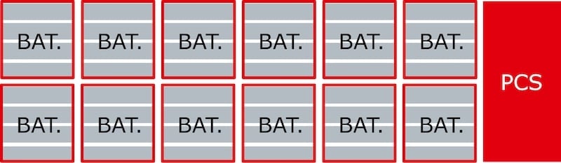
Figure 1. BESS container with central inverter. Image used courtesy of Bodo’s Power Systems [PDF]
The modular PCS approach (Figure 2) is the current trend to resolve these issues. The same 20-foot container is used, but each rack of batteries has its own dedicated inverter. This improves serviceability, as only one subset of batteries is taken offline when a PCS failure occurs. Furthermore, it is now possible to change the system power rating in increments of one battery rack without worrying about the inverter being oversized for the application.
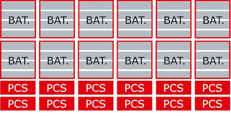
Figure 2. BESS container with modular PCS. Image used courtesy of Bodo’s Power Systems [PDF]
Advancements in battery technology are also influencing PCS sizing. Lithium-ion (Li-ion) remains the predominant battery type. However, there have been consistent developments in material optimization, electrolyte innovations, and manufacturing technology. New Li-ion types, such as cobalt-free Lithium Iron Phosphate (LFP), allow 5 MWh of capacity in a 20-foot container. Recent improvements will push this power rating to 6 MWh and beyond in the next few years.
While the “energy capacity” of the BESS is one value (e.g., 6 MWh), the “rated power capacity” of the system for charging/discharging is lower. This is the power level at which the entire system could be instantaneously discharged starting from a full charge. A fractional value, designated with a P or C, defines this rate and, hence, the power rating of the PCS.
At a 0.5C charge/discharge rate, this means that the PCS in a 6 MWh BESS needs to be rated for 3 MW continuous operation. With the 12-rack topology shown in Figure 2, a power rating of approximately 250 kW per PCS is needed. Couple this with the fact that a modern rack-mounted PCS must fit into a standard 19” wide rack, and it is clear that power density becomes a driving factor when designing a power converter. Additionally, critical requirements for the PCS are as follows:
- Ability to accept up to 1500 VDC continuously
- High efficiency over charging (PF = -1) and discharging (PF = 1) modes
- Power dense (liquid cooling)
- Withstand repeated system (long) charge/discharge cycles
Power Conversion System Design
Today, the most effective topology for meeting the electrical requirements is the 3-level, active neutral point clamped (ANPC) converter. The 3-level configuration can accommodate the 1500 V bus voltage using low loss 1200 V semiconductors. The ANPC configuration (as opposed to the NPC type) offers equally high efficiency when the battery is charging (PF = -1) and discharging (PF = 1).
The SEMITOP E2 power module from Semikron Danfoss packages all six switches in an ANPC phase leg into a compact footprint (57 mm x 63 mm). Press-fit or solder pins allow for easy PCB mounting. The one-piece housing with integrated mounting tabs applies high mounting pressure to the heatsink. This mechanical design feature alone provides a superior thermal resistance, Rth(j-s), to industry standard modules. However, the SEMITOP E2 is also available with pre-applied high performance thermal paste (HPTP) or phase change material (HP-PCM) in an optimized pattern for bestin-class thermal performance. A baseplate-less design strongly benefits from a liquid cooled heatsink and minimizes the thermal layers between the chips and coolant. The lack of baseplate and the associated solder layer means that the module is resilient against thermal cycles that come with each charge and discharge event.
Since control methodology of the ANPC converter strongly affects individual switch losses, the power module must be designed with chips optimized for either conduction or switching losses in each switch position. The 150A ANPC SEMITOP E2 (Figure 3) is designed for the Low Frequency/High Frequency (LF/HF) switching scheme. This means that the four switches in positions T1, T5, T6, and T4 are Generation 7 high power IGBTs. These IGBTs are designed for low conduction losses as they only switch with the line frequency. The two switches in positions T2 and T3 are the latest generation silicon carbide MOSFETs. The switches in these positions operate at a high carrier frequency and must exhibit low switching losses. This hybrid approach allows for high frequency switching for LF/HF configurations while keeping the overall module cost low.
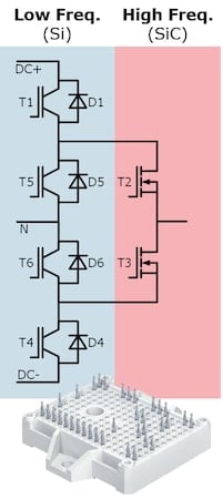
Figure 3. SEMITOP E2 module (e.g. SK150AMLI120CR03TE2). Image used courtesy of Bodo’s Power Systems [PDF]
The specification for a futurelooking, modular PCS used in multi-MW class containers is given in Table 1. This has been used as the basis for a thermal simulation of a PCS design using the SEMITOP E2 module.
Table 1. Next generation modular PCS specification.
| Parameter | Value |
| VDC [V] | 1500 |
| VAC [V] | 690 |
| IAC [A] | 209 |
| Grid frequency [Hz] | 50 |
| Power [kW] | 250 |
| Cooling | Liquid, Tcoolant = 50 °C |
To meet the target power output and charge/discharge lifetime while still maintaining adequate efficiency, two SK150AMLI120CR03TE2 are used in parallel to construct each of the three phase legs. These have been placed on a hypothetical water-cooled heatsink (Figure 4) with a total Rth(s-a) of 0.0146 K/W. All six modules fit within a 400 mm x 58 mm footprint.
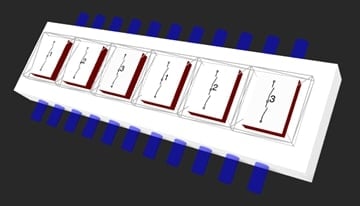
Figure 4. Simulated hypothetical water-cooled heatsink configuration for six SEMITOP E2 modules (2 per phase). Image used courtesy of Bodo’s Power Systems [PDF]
The results (Figure 5) show that semiconductor efficiencies above 99 % can be achieved across a switching frequency range of 10…20 kHz while either charging or discharging.
A Modular PCS for Everyone
Design of a complete PCS requires a knowledge of 3-level power converter control, as well as system and application knowledge to ensure that the PCS interacts properly with the whole BESS. This is where a power electronics developer experienced with renewable energy resources is helpful. Semikron Danfoss is partnering with Headspring Inc. of Tokyo, Japan to develop an exemplary PCS around the SEMITOP E2 module.
Headspring is developing the ANPC control software to drive the power modules using their high-speed real-time controller system. This controller will also integrate connections with the BESS battery management system (BMS), as well as functions for a codecompliant grid-tied connection. An option for standalone mode is available as well, which allows the BESS to function as a reliable backup power source during grid outages.
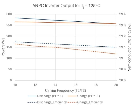
Figure 5. Output power and efficiency of ANPC inverter (semiconductor losses only). Image used courtesy of Bodo’s Power Systems [PDF]
Each PCS module has its own controller designed to seamlessly integrate with other PCS modules connected in parallel. This provides the scalability needed to drive the entire BESS container as well as providing continued system operation in case of failures of individual PCS modules. Headspring is also experienced with designing filters and protection circuits necessary for the PCS.
For the power converter hardware, Semikron Danfoss can provide design support to integrate SEMITOP E2 power modules with Headspring control systems. With this collaboration, anyone building utility scale BESS can get access to a next-generation modular PCS design.
Advances in application requirements and battery technology are changing the way high-power battery energy storage systems are designed. A modular PCS block based on the ANPC topology is presently the optimal alternative.
This article originally appeared in Bodo’s Power Systems [PDF] magazine.