Facebook
 Google
 GitHub
 Linkedin
HV-IGBT Module for High-Performance Inverter Design
Learn about Mitsubishi’s XB-Series HV-IGBT modules. They offer lower switching losses and enhanced reliability through 7th-gen Si IGBT and RFC diodes, improving inverter efficiency.
This article is published by EEPower as part of an exclusive digital content partnership with Bodo’s Power Systems.
Article co-authored by Mitsubishi Electric’s Nils Soltau, Shuhei Saito, and Hironaka Yoichi.
To meet growing demands for energy-efficient and reliable inverter systems in traction applications, Mitsubishi Electric has introduced the XB-Series high-voltage IGBT modules, engineered for use in harsh environments such as railway systems and medium-voltage drives [1].
The XB-Series represents the latest generation of HVIGBT modules from Mitsubishi Electric. While the X-Series targets applications requiring the highest power density and performance, the XB-Series was specifically engineered as a value-optimized solution focused on both reliability and efficiency.
It is designed for converter systems that require high switching speed or utilize earlier generations of IGBTs, such as the R- and H-Series. The current ratings of the XB-Series are optimized to serve as a practical and efficient replacement for these legacy HVIGBT modules.
This article presents the key advantages of adopting the XB-Series, particularly in terms of improving the reliability and overall performance of high-voltage power converters.
Lineup Overview
The product lineup includes a range of modules with rated blocking voltages of 3.3 kV, 4.5 kV, and 6.5 kV with package isolation voltages of 6.0 kV and 10.2 kV, and current ratings up to 1500 A–covering a wide spectrum of traction inverter applications (Table 1). Both package types, offering 6.0 kV or 10.2 kV isolation voltages, are illustrated in Figure 1 [2].
The external dimensions of the new XB-Series remain identical to those of the previous R-Series. As a result, isolation voltage, physical footprint, and maximum junction temperature are consistent with the conventional 3.3 kV R-Series. This design allows seamless replacement without the need for modifications to the interface, such as busbars or mounting configurations.
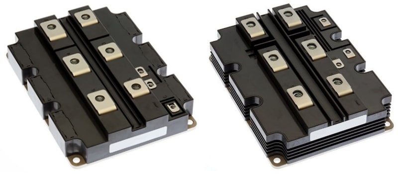
Figure 1. XB-Series HVIGBT modules in 6.0kV and 10.2kV isolation packages. Image used courtesy of Bodo’s Power Systems [PDF]
| Type name | Rated voltage | Rated current | Isolation Voltage | Maximum junction temperature |
| CM1500HC-66XB | 3.3 kV | 1500 A | 6.0 kVrms | 150 °C |
| CM1200HC-90XB | 4.5 kV | 1200 A | 6.0 kVrms | 150 °C |
| CM1200HG-90XB | 4.5 kV | 1200 A | 10.2 kVrms | 150 °C |
| CM750HG-130XB | 6.5 kV | 750 A | 10.2 kVrms | 150 °C |
Table 1. Lineup of XB-Series HV-IGBT
Electrical Performance
Switching and static losses are among the most critical performance parameters of IGBT modules, as they directly impact inverter efficiency and thermal management. With each new generation of HVIGBTs, Mitsubishi Electric aims to incorporate cutting-edge technologies into chip design to minimize these losses.
As shown in Figure 2, the XB-Series achieves approximately 15% lower total power losses [3] in acceleration mode (power factor PF = 0.85) compared to the previous R-Series. According to the simulation, the same result of 15% reduction of power losses may be expected for the braking mode.
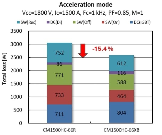
Figure 2. Total inverter loss calculation result. Image used courtesy of Bodo’s Power Systems [PDF]
This significant improvement is primarily achieved by optimizing gate structure, which reduces the reverse transfer capacitance (Cres). While the conventional 3.3 kV R-Series utilized a planar gate design, the new XB-Series employs a trench gate, resulting in a more favorable distribution of hole density in the collector region—both at the top and bottom surfaces of the IGBT chip.
That allows XB-Series to have a 77% reduction in input capacitance (Cies) and a 49% reduction in reverse transfer capacitance (Cres) compared to the R-Series. Additionally, the total gate charge (QG) is reduced by approximately 51%, which not only contributes to lower switching losses but also facilitates the miniaturization and energy efficiency of the gate driver unit.
Reliability of IGBT and Diode Chips
Since the primary target applications of HVIGBTs are traction systems and railway converters, reliability and robustness are top priorities. These systems operate under high voltage, variable load, and harsh environmental conditions where unexpected faults or overloads may occur. A traditional measure of IGBT robustness is the Safe Operating Area (SOA), which defines the limits under which the device can safely operate without failure.
Although the maximum specified turn-off current is typically twice the nominal current, the new XB-Series IGBT chip is capable of safely turning off more than 6.5 times its nominal current (9750 A), as demonstrated on the CM1500HC-66XB example in Figure 3.
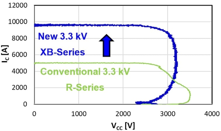
Figure 3. Comparison of I-V plots. Image used courtesy of Bodo’s Power Systems [PDF]
The conventional 3.3 kV R-Series used a Field Limiting Ring (FLR), which caused high electric field concentration at the edge during turn-off, risking avalanche breakdown. In contrast, the XB-Series uses a Linearly-narrowed Field Limiting Ring (LNFLR) that gradually narrows the P-type region, reducing hole injection and current crowding. This helps to relax the electric field at the termination and improves switching robustness.
The diode chip structure in the XB-Series was also optimized by implementing Relaxed Field Cathode (RFC) technology, which effectively suppresses snap-off effect during reverse recovery – even under high turn-on di/dt conditions [4]. As a result, the XB-Series demonstrates approximately 3.9 times higher reverse recovery peak power (Prr) than the specified datasheet limit, significantly enhancing diode robustness and system reliability.
Lifetime Improvement
One of the primary aging mechanisms that limits the lifetime of power semiconductor modules is mechanical stress induced by thermal cycling. Due to the differing coefficients of thermal expansion (CTE) among materials, each heating and cooling cycle causes incremental degradation of internal connection joints. In the conventional R-Series, the solder joints beneath the power terminals were identified as the key failure point.
As thermal fatigue leads to crack propagation in these joints, electrical resistance increases, resulting in uneven current distribution across the module and a corresponding rise in collector-emitter saturation voltage (VCE(sat)).
To enhance the mechanical durability of these joints, a high-strength solder alloy was introduced in the XB-Series. This solder offers improved fatigue resistance under shear stress, significantly extending the module’s thermal cycling lifetime. The results of the thermal cycling test are presented in Figure 4, where the failure criterion was defined as a 5% increase in VCE(sat).
As shown, the normalized number of cycles before failure is more than twice as high for the XB-Series compared to the 3.3 kV R-Series, demonstrating substantial improvement in long-term reliability.
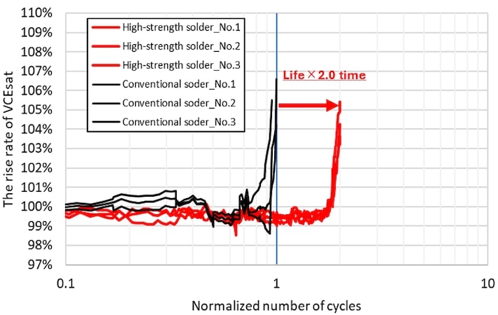
Figure 4. Thermal Cycling Lifetime Comparison. Image used courtesy of Bodo’s Power Systems [PDF]
Conclusion
The newly developed XB-Series HV-IGBT modules by Mitsubishi Electric provide a highly reliable and efficient solution for traction and medium-voltage inverter applications. Featuring advanced chip and packaging technologies, the XB-Series achieves approximately 15% lower switching losses and significantly improved robustness compared to previous generations.
Enhanced Safe Operating Area (SOA), improved diode recovery behavior, and extended thermal cycling lifetime make the XB-Series well-suited for demanding environments. The modules also maintain full mechanical compatibility with legacy products, enabling easy system upgrades.
Together, the XB-Series and X-Series form a comprehensive HVIGBT product family that supports a broad range of applications. The XB-Series targets high switching speed systems and offers current ratings aligned with previous HVIGBT generations, making it ideal for upgrades. In contrast, the X-Series provides higher current capability and is optimized for applications requiring maximum power density. This flexibility enables Mitsubishi Electric to support both legacy system modernization and next-generation power electronics development.
References
[1] S. Saito, S. Tokumaru, Y. Hironaka, N. Soltau, V. Tolstopyatov and K. Hatori, "New 3.3 kV HV-IGBT Module for High-Speed Switching," PCIM Conference 2025, Nürnberg, Germany, 2025, pp. 817-823
[2] Mitsubishi Electric Press Release No. 3786, Mitsubishi Electric to Ship Samples of XB Series HVIGBT Module, Tokyo, April 11, 2025.
[3] Mitsubishi Electric. “Power Loss Simulation Software. ”MitsubishiElectric.com. Accessed: Jul. 8, 2025. [Online.] Available: https://www.mitsubishielectric.com/semiconductors/powerdevices/design_support/simulator/
[4] A. Nishii, K. Nakamura, F. Masuoka and T. Terashima, "Relaxation of current filament due to RFC technology and ballast resistor for robust FWD operation," 2011 IEEE 23rd International Symposium on Power Semiconductor Devices and ICs, San Diego, CA, USA, 2011
This article originally appeared in Bodo’s Power Systems [PDF] magazine and is co-authored by Victor Tolstopyatov, Nils Soltau, Mitsubishi Electric Europe B.V., Germany, and Shuhei Saito, Hironaka Yoichi, Mitsubishi Electric Corporation, Japan.