 Facebook
 Google
 GitHub
 Linkedin
Understanding Resistance Measurement Tools
Learn about resistance measurement through two methods: the Ammeter/Voltmeter approach and the megohmmeter. The Ammeter/Voltmeter method uses standard electrical instruments, while the megohmmeter is designed specifically for high-resistance measurements.
Two primary methods are employed in resistance measurement: the ammeter/voltmeter approach and the specialized megohmmeter. The ammeter/voltmeter method measures resistance by measuring voltage and current across a resistor, though errors can arise based on the connection arrangement. On the other hand, the megohmmeter is specialized for high-resistance measurements. It is available in two versions: the hand-cranked and battery-powered variants, each offering specific advantages for precise resistance assessment in diverse electrical applications.
Image used courtesy of Freepik
Ammeter/Voltmeter Methods
If the voltage across a resistor and the current flowing through it are measured, the resistance value can be calculated by applying Ohm's law. However, an error occurs depending on how the ammeter and voltmeter are connected, and this error may be insignificantly small or large enough to be important.
Consider the arrangement shown in Figure 1(a). Because the voltmeter is connected directly across Rx, it measures the actual resistor voltage. However, the ammeter measures the resistor current Ix and the current Iv that flows through the voltmeter. Using the voltage and current measurements, we can calculate a resistance value as follows:
\[Calculated\,Resistance=\frac{Voltmeter\,Reading}{Ammeter\,Reading}\]
\[R_{X1}=\frac{V_{X}}{I_{X}+I_{V}}\]
Equation 1.
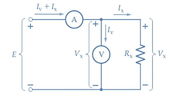
(a) Ammeter measuring Iv + Ix
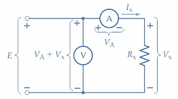
(b) Voltmeter measuring VA + Vx
Figure 1. Errors can occur when resistance is measured using an ammeter and voltmeter. To minimize errors, the voltmeter should be connected directly across Rx when Rx is low, and the ammeter should be directly in series with Rx when Rx is high. Image used courtesy of Amna Ahmad
The actual resistance of Rx is Rx = Vx/Ix, so the presence of Iv in the equation introduces an error in the result. If Iv is much smaller than Ix, the error may be insignificant. This requires that Ix be a large current, which is the case when Rx is a small resistance.
Now consider the arrangement illustrated in Figure 1(b), where Rx and the ammeter are in series, and the voltmeter is connected in parallel with the two of them. In this case, the ammeter measures the actual current through Rx, but the voltmeter measures the voltage across Rx plus the voltage across the ammeter. Using these two measurements, the resistance is calculated as:
\[R_{X2}=\frac{V_{X}+V_{A}}{I_{X}}\]
Equation 2.
Again, the actual resistance of Rx is Rx = Vx/Ix, and consequently, the presence of VA in Equation 2 produces an error in the result. The error could be insignificant if VA is much smaller than Vx. This requires that Vx be a large voltage, which means that Rx should be a large resistance.
The voltmeter should be connected directly across Rx for the greatest accuracy when Rx has a small resistance. For the greatest accuracy when Rx has a large resistance, the ammeter should be connected directly in series with Rx. The correct arrangement can be easily determined by first connecting the ammeter in series with Rx, then observing the ammeter reading with the voltmeter temporarily connected directly across Rx [i.e., connected as in Figure 1(a)]. If the ammeter reading is not noticeably altered when the voltmeter is connected, the readings will give an accurate result. When the ammeter reading is noticeably changed by connecting the voltmeter, the voltmeter should be moved to the other side of the ammeter.
Example 1
An ammeter and voltmeter connected as in Figure 1(a) indicate 10 A and 99 V, respectively. When the voltmeter is changed to reconnect the circuit, as in Figure 1(b), the readings become 10 A and 100 V. The ammeter has a resistance of 0.1 Ω. The voltmeter is on its 100 V range and its sensitivity is 20 kΩ/V. Calculate the measured resistance for each case and determine which arrangements give the most accurate result.
Solution
For the circuit of Figure 1(a)
\[R_{X}=\frac{V_{X}}{I_{X}+I_{V}}=\frac{99V}{10A}=9.9\Omega\]
The voltmeter resistance is
\[R_{V}=\frac{20k\Omega}{V}\times(voltmeter\,range)=\frac{20k\Omega}{V}\times100V=2M\Omega\]
\[I_{V}=\frac{V_{X}}{R_{V}}=\frac{99V}{2M\Omega}=49.5\mu A\]
So
\[I_{V}<
For the circuit of Figure 1(b)
\[R_{X}=\frac{V_{X}+V_{A}}{I_{X}}=\frac{100V}{10A}=10\Omega\]
And
\[V_{A}=I_{A}R_{A}=10A\times0.1\Omega=1V\]
In this case, VA is not much smaller than Vx, so the connection shown in Figure 1(a) gives the most accurate result.
Example 2
The insulation resistance of an electrical cable is to be measured using a 1000 V source, a 1500 V voltmeter with a sensitivity of 10 k/V, and a 500 A ammeter with a resistance of 100. If the insulation resistance is 5 M, determine the measured resistance using the two methods of connecting the instruments.
Solution
Connection (a)
Ix = 1000 V/5 MΩ = 200 µA
Rv = 1500 V × 10 kΩ/V = 15 MΩ
Iv = 1000 V/15 MΩ = 66.7 µA
Measured R = V/ (Ix + Iv) = 100 V/ (200 µA + 66.7 µA) = 3.75 MΩ
Connection (b)
Ix = 1000 V/ (5 MΩ + 100 Ω) ≈ 200 µA
Measured R = V/Ix = 1000 V/200 µA = 5 MΩ
Megohmmeters for Resistance Measurement
The megohmmeter, commonly referred to as a megger, measures exceptionally high resistances, such as the insulation resistance in electrical cables. To achieve this, a high-voltage source is necessary to pass a measurable current through these resistances. In essence, a megger functions like an ohmmeter but employs a low-current instrument and a high-voltage source. As depicted in Figure 2(a), the voltage is typically generated using a hand-cranked generator, ranging from 100 V to 2.5 kV.
Similar to a low-resistance analog ohmmeter, the megger's scale reflects specific values. When measuring an open circuit, it shows infinity (∞), zero for a short circuit, and half-scale when the unknown resistance matches a standard resistor within the megohmmeter. For other positions on the scale, the deflection is directly proportional to the ratio of the unknown and standard resistors. The instrument's range is adjustable by switching various standard resistor values into the circuit.
Megohmmeters operating on battery power are also available, essentially functioning as ohmmeters for very high resistance values. Figure 2(b) illustrates one such instrument. The battery voltage is typically increased to around 1000 V using electronic circuitry to generate a measurable current through the unknown resistance. The measurement is taken by pressing and holding the power button briefly, an arrangement that reduces the current drain on the battery.

Hand-cranked megohmmeter
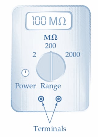
Battery-powered megohmmeter
Figure 2. A megohmmeter (megger) is essentially an ohmmeter for measuring very high resistances. A high-voltage source and a low-current meter are required. Image used courtesy of Amna Ahmad
Resistance Measurement Takeaways
Two primary methods for measuring resistance are the ammeter/voltmeter and the specialized megohmmeter approach. The ammeter/voltmeter approach calculates resistance by measuring voltage and current across a resistor, but circuit connections may affect its accuracy. On the other hand, the megohmmeter is specifically designed for high-resistance measurements and is available in two versions: hand-cranked and battery-powered. The hand-cranked megohmmeter operates using a hand-cranked generator to measure high resistances. Conversely, the battery-powered megohmmeter offers convenience and efficiency, enabling accurate measurements while minimizing current drain through a press-and-hold mechanism.


Below figure (a), it’s shown resistance Rx = Vx/(Iv + Ix). That’s incorrect. The current Iv and Ix are separate from each other at least as long as V the voltmeter are in the circuit, where Iv is the current through the Voltmeter V, and the current Ix is the current through the resistor Rx. Current Iv does not flow through Rx. The current flowing through V the voltmeter may be significantly different than the current flowing through Rx. Therefore, Rx = Vx/Ix. So the only way the equation in figure (a) would be correct is if the current Iv = 0, which would presume an ideal voltmeter that uses absolutely no current in its coil/meter movement, which of course is not true in reality.