Facebook
 Google
 GitHub
 Linkedin
EPC Intros GaN-Based Inverter Board for Robotics, E-Mobility
The integrated three-phase BLDC motor drive inverter integrates control, sensing, and communication to deliver up to 20 ARMS for humanoid joint motors.
Efficient Power Conversion (EPC) has released the EPC91122, a compact 3-phase BLDC motor drive inverter evaluation board for humanoid robot joints, drones, and e-mobility applications.
The board could help humanoid robot designers navigate the mechanical and electrical constraints of joint drives. It integrates a complete gallium-nitride (GaN) based power stage, control, sensing, and communication system into a 32 mm-diameter circular form factor.
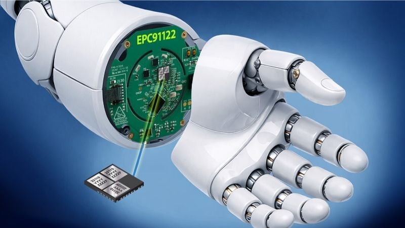
The evaluation board in a robotic joint. Image used courtesy of EPC
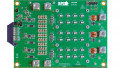
The EPC91122 Eval Board
EPC built the EPC91122 around its EPC33110, a 100 V maximum, three-phase ePower Stage module that co-packages three monolithic GaN half-bridges with integrated gate drivers, bootstrap circuits, and level shifters. The module features RDS(on) values of 11.7 mΩ and 13 mΩ and supports switching frequencies up to 150 kHz, enabling designers to reduce passive component size and improve current-control bandwidth.
The board operates on a 15 to 65 VDC input range and can deliver up to 20 ARMS (28 Apk) phase current in pulsed operation when installed inside a humanoid joint. Under steady-state conditions, thermal characterization shows that the inverter can supply 7 ARMS per phase without a heatsink at 48 V and 100 kHz PWM, maintaining less than 80°C temperature rise from the eGaN IC case to ambient.
When the motor casing acts as a heatsink with a 1 mm electrically non-conductive thermal interface material, the board can support up to 15 ARMS per phase under the same conditions with a temperature rise below 70°C.
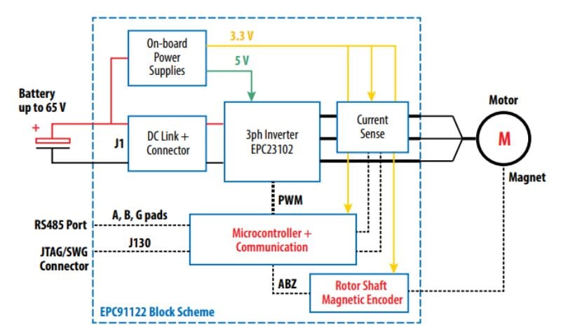
Block diagram of the EPC91122. Image used courtesy of EPC
Mechanically, the complete GaN inverter occupies a 32 mm diameter inner circle, surrounded by a 55 mm external frame that provides mounting and lab connectivity. According to the company, this geometry helps designers mount the inverter directly within the stator assembly to reduce loop inductance between the DC-link capacitors and the power stage.
The board includes 18 multilayer ceramic capacitors for the DC link as well as current sensing on phases U and V using MCS1823-330BRN devices with 44 mV/A gain. A resistor divider network with 44.89 mV/V gain measures the DC bus and phase voltages. The current sensors include overcurrent detection outputs connected to the microcontroller in a wired-OR configuration.
Further integration features include control and communication functions on the board. Specifically, a 7 x 7 mm STM32G431CBU6 microcontroller manages PWM generation, feedback processing, and communication, and operates at a default 100 kHz PWM with 50 ns dead time.
Meanwhile, a rotor shaft magnetic encoder located at the board’s center provides 1024 pulses per revolution with a Z index for position reference. An RS485 interface and a 14-pin JTAG/SWD connector support communication for firmware development and debugging.
High-Frequency GaN Switching in Motor Drives
Switching frequency strongly influences motor drive inverters’ size, response time, and efficiency. In traditional silicon-based systems, designers often limit PWM frequencies to tens of kilohertz to contain switching losses and thermal stress. Higher frequencies reduce current ripple and allow smaller inductors and capacitors, but they increase switching loss in silicon MOSFETs due to charge storage and slower transition times.
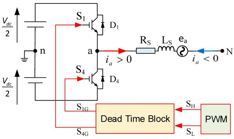
A-phase leg of three-phase inverter with the dead-time block. Image used courtesy of Poolphaka et al.
Gallium nitride devices differ fundamentally in structure and carrier dynamics. Enhancement-mode GaN FETs are majority-carrier devices lacking reverse-recovery charge associated with body diodes in silicon MOSFETs. As such, it reduces switching losses during hard commutation in half-bridge configurations. Meanwhile, lower gate charge and output capacitance enable faster voltage transitions with controlled dead time.
In three-phase inverters, higher PWM frequencies can reduce torque ripple and improve current loop bandwidth. However, increasing frequency tightens layout constraints. Parasitic inductance between the DC link capacitors and switching nodes can produce voltage overshoot and ringing.
To solve this issue, engineers can use co-packaged modules that integrate half-bridges, drivers, and bootstrap circuits in a co-packaged module to shorten current paths and reduce loop area. When designers physically place the inverter inside the motor housing, they further reduce cable inductance and electromagnetic interference and improve switching stability at 100 kHz and above.
Embedded Intelligence in Robotic Actuators
The EPC91122 is available as a reference design board and is offered through distribution. By offering complete design files, including schematics, bill of materials, and Gerber data, EPC aims to provide developers with a starting point for integrating high-frequency GaN motor drives directly into robotic joints.