Facebook
 Google
 GitHub
 Linkedin
Inverter Efficiency: Navigating Measurement Challenges in SiC- and GaN-Driven Systems
If your power inverter measurements show an efficiency of more than 100%, or the measured values sound too good to be true, it could mean you found the holy grail. More likely, there is a measurement error caused by phase shift. With the introduction of SiC and GaN semiconductors in inverter drives, switching frequencies have increased considerably, making electrical power measurement more challenging. This article examines the challenges and possible solutions.
This article is published by EEPower as part of an exclusive digital content partnership with Bodo’s Power Systems.
Have you ever measured an efficiency of more than 100% on a SiC-based inverter and thought you found a way to create energy with the inverter? It is more likely this was due to incorrect power measurement caused by a measurement error in the phase difference between the voltage and the current. This is common if your power measurement system is not ready to measure high-frequency applications reliably. Your power analyzer is, of course, still good enough to evaluate the efficiency of inverters with a switching frequency of up to 10k Hz because, at this frequency level, the phase error has a smaller impact. However, these power analyzers will not give accurate and repeatable results at switching frequencies up to 100 kHz for SiC-based applications and even above 1 MHz for GaN-based applications.
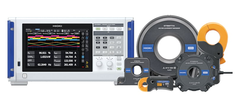
Figure 1. The complete solution is the PW8001 power analyzer with HIOKI current sensors. Image used courtesy of Bodo’s Power Systems [PDF]
Traditional power analyzers, utilizing internal measurement shunts for current measurement are not suitable for measuring current at high frequencies because the shunts’ inductive properties influence the amplitude and phase accuracy at these high frequencies. This is even more noticeable when higher currents must be measured, and external zero flux current sensors are required. The sensors, as such, may have sufficient accuracy, but these current sensors are typically produced by a different manufacturer than your power analyzer, and they are, therefore, not optimized for each other.
New Measurement Methods Designed for SiC and GaN
The HIOKI solution combines a HIOKI power analyzer with external HIOKI zero flux current sensors, designed for accurate power measurement with unique features to optimize high-frequency power measurement. The most important feature is the phase shift compensation function to reduce the influence of phase errors.
For a phase shift compensation function to work properly, you need two things:
- A power analyzer makes the correct phase adjustment
- A current sensor with a known phase shift
A good way to explain the compensation in the power analyzer is by comparing it to the “deskew” function of an oscilloscope: If two different signals arrive at the oscilloscope at different times due to latencies, then the “deskew” function lets you align those signals by compensating the latency with a fixed time value.
The phase shift compensation is basically the same because the phase error is directly related to the time delay of the current sensor. As an example, here is how this delay looks for a HIOKI CT68xxA series current sensor. The time delay is shown in nanoseconds against the frequency:

Figure 2. Stable time delay of HIOKI CT68xxA current sensors. Image used courtesy of Bodo’s Power Systems [PDF]
100 ns delay at 100 Hz doesn’t have the same impact as 100 ns delay at 1 MHz. This becomes clear when transforming the above time delay into phase delay values described in degrees:
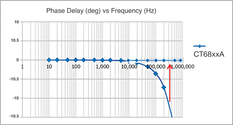
Figure 3. Phase delay vs. frequency. Image used courtesy of Bodo’s Power Systems [PDF]
To address this phase delay, you need a current sensor where the time delay is the same regardless of the frequency. This is the case with the HIOKI current sensors that also automatically communicate the value of the phase delay to the power analyzer. Returning to the “deskew” function, you only need to connect the current sensor to the PW8001 power analyzer, and the phase error will be compensated automatically.
This is one characteristic that makes HIOKI sensors unique–but it is not standard for all current sensors on the market. Here is what would happen with a typical current sensor:
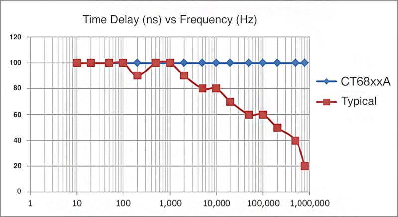
Figure 4. Typical sensors compared to the HIOKI CT68xxA series. Image used courtesy of Bodo’s Power Systems [PDF]
A sensor with different time delay values depending on the frequency will make the phase shift compensation in a power analyzer almost impossible. Because which value do you use as your “deskew” parameter?
Another feature that makes HIOKI current sensors unique is that the position of the wire core does not influence the phase delay:
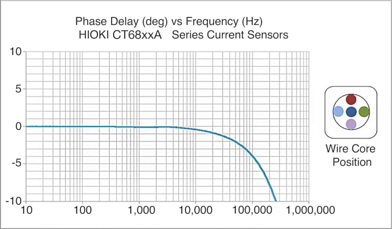
Figure 5. HIOKI CT68xxA’s phase delay and wire core position. Image used courtesy of Bodo’s Power Systems [PDF]
You can only see one line in the chart because the phase delay curves for all five measurement positions are the same, which does not leave room for errors. Again, this is not a standard feature for current sensors. Typically, the position of the wire core within the sensor will affect the phase error, as you can see in the below graph:

Figure 6. Typical sensor’s phase delay and wire position. Image used courtesy of Bodo’s Power Systems [PDF]
Optimal for Applications up to 5 kV
If you are working with high frequency and higher voltage applications, there is a solution that further covers this area: a highly accurate high voltage divider. The capability to precisely measure power up to 5 kV represents a significant advancement in accuracy compared to existing solutions utilizing differential probes. This is particularly beneficial for high voltage and high-frequency applications involving SiC and GaN semiconductors because of its 4 MHz bandwidth and a known phase error, making it possible to compensate for the phase error in the power analyzer.
The Key to Purposeful Measurements
The repeatability of measurement results is essential to draw conclusions. HIOKI Engineers at our HQ in Japan have measured the efficiency of a SiC-based inverter using the PW8001 power analyzer in combination with the 50 A AC/DC sensors CT6872 over 30 seconds. The switching frequency of the SiC semiconductors was 50 kHz, and the motor was at a constant speed of 1000 rpm. The integration time for the measurement was set to 200 ms, and the motor current in this experiment was approximately 2 A. The graph below shows the excellent stability of the measurement:
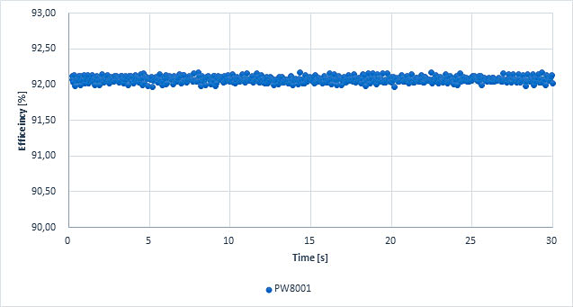
Figure 7. Efficiency measurement of a SiC inverter at 50kHz: excellent repeatability. Image used courtesy of Bodo’s Power Systems [PDF]
The difference between the maximum and minimum results over the 30 seconds was less than 0.2%. This experiment demonstrates that even at low currents, this setup delivers excellent repeatability, which is key in the development stage because it identifies even small efficiency gains due to changes in the design. However, such accurate results can only be achieved with an effective phase shift compensation.
Under the same test conditions, two well-known suppliers of power measurement systems have been tested. The outcome is shown in Figure 8:

Figure 8. Efficiency measurement of a SiC inverter at 50kHz: poor repeatability. Image used courtesy of Bodo’s Power Systems [PDF]
In this case, the repeatability of the measurements is a lot worse. The difference between the maximum and minimum efficiency is more than 1% for both systems. This makes it very hard for engineers to conclude whether the changes they make in their designs have an effect. For instance, even if you measure an increase in efficiency of 0.9%, this might be caused by poor measurement repeatability, and you might not have achieved an increase in efficiency after all.
A Measurement System From One Source
For an effective phase shift compensation, you need a power analyzer with a phase shift compensation function and a current sensor with stable and known time delay characteristics at high frequencies. The PW8001 power analyzer even features automated phase shift compensation, allowing it to automatically recognize the current sensor and adjust the phase compensation accordingly using the data provided by the sensor.

Figure 9. Automatic sensor detection and retrieval of information by the power analyzer PW8001. Image used courtesy of Bodo’s Power Systems [PDF]
HIOKI has been designing and producing current sensors for power measurement for many years, and time delay characteristics have always been a design focus for our engineers. On the other hand, zero flux current sensors from different manufacturers are typically designed for accurate current sensing where time delay characteristics are less important. Therefore, HIOKI power analyzers and zero flux current sensors are a combination for wideband power analysis applications from DC to high frequency—an accurate power measurement system from one source.
This article originally appeared in Bodo’s Power Systems [PDF] magazine and is co-authored by Kai Scharrmann, head of sales, and Roy Hali, head of product management, HIOKI.