Facebook
 Google
 GitHub
 Linkedin
Three-Phase Module Based on Monolithic Gan Half-Bridge ICs
Learn about the EPC33110, a three-phase module that uses GaN monolithic ICs. It enables the development of smaller, lighter motor drive inverters.
Article co-authored by EPC's Marco Palma.
This article is published by EEPower as part of an exclusive digital content partnership with Bodo’s Power Systems.
The EPC33110 is a cutting-edge three-phase module leveraging gallium nitride (GaN) technology, representing an innovative solution in power electronics for motor drive applications. GaN devices, known for their superior electrical properties compared to traditional silicon-based components, enable the EPC33110 to deliver exceptional performance in a compact form factor.
GaN technology enables the integration of the logic functions and gate driver on the same substrate as the power FETs, thanks to the lateral conduction of the power devices, allowing the realization of monolithic power half-bridge chips. The EPC33110 implements the co-packaging of three half-bridges, keeping the excellent electrical and thermal performance of GaN devices, while optimizing the overall size of the inverter.
This module is specifically designed to meet the stringent requirements of applications such as drones and humanoid robots, where size, weight, efficiency, and thermal management are critical constraints. Its compact form and ease of use simplify the designer’s approach to miniature motor drive inverters in complex structures, such as multi-axis motor drives in humanoid arms.
EPC33110 Description
The EPC33110 is a three-phase co-packaged module that integrates three monolithic gallium nitride (GaN) half-bridges, each featuring integrated gate drivers, bootstrap circuits, and level shifters. This integration results in a compact, high-power-density solution optimized for motor control applications. The module operates with a maximum recommended input voltage of 80 V and exhibits a typical on-resistance of 8.7 mΩ at room temperature for each power GaN FET.
Designed to support logic-level inputs at 3.3 V or 5 V, the EPC33110 simplifies system design by eliminating the need for discrete gate driver components. By embedding the gate driver within the module, it enables a logic-input-to-power-output configuration, which reduces the component count and overall system complexity.
This design approach requires only a minimal set of external components: small bypass capacitors to stabilize the power supply of the three legs, a single decoupling capacitor for the low-side power FETs driving stage, and three bootstrap capacitors to drive the high-side FETs. Co-packaging three integrated half-bridges ICS enhances power density and exhibits a good thermal performance thanks to the excellent top-side cooling obtained by the exposed dies.
The EPC33110 is housed in a 6x6.5 mm QFN package featuring 21 pads, which include 7 signal pins, 7 supply pins, 7 power pads and is represented in Figure 1. It supports six complementary PWM signals and includes a fast, active-low shutdown pin to disable the module during fault conditions.
The whole module is supplied at 5 V by a single pin VDRV, which powers the three supplies of the logic circuits VDD internally, which must be locally decoupled by small capacitors. The VDRV also charges the bootstrap capacitors through a synchronous boot FET; the bootstrap pins are conveniently positioned close to their respective switching node pads.
Additionally, the device has three switching node power pads, two power pads for ground (GND), and two power pads for Vin. The complementary input PWM signals are designed to optimize dead time based on the application. Meanwhile, the large Vin, power GND, and switching node pads reduce PCB trace resistance and inductance, thereby enhancing thermal dissipation through the PCB.
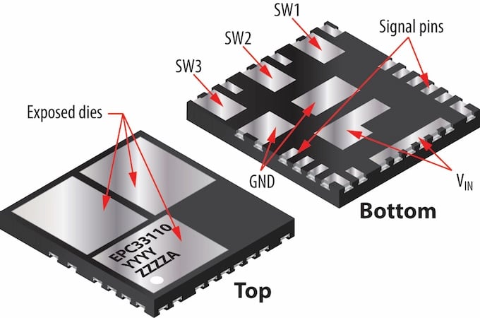
Figure 1. Overview of the top side (left) and bottom side (right) of the EPC33110 module. Image used courtesy of Bodo’s Power Systems [PDF]
Motor Drive Application
The EPC33110 is specifically designed for driving three-phase permanent magnet motors, which are widely used in applications such as drones and humanoid robots due to their efficiency, compact size, and precise control capabilities.
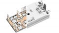
Complementing the EPC33110 module, the EPC91122 reference design board serves as a practical implementation platform tailored for humanoid robot joints and small drone applications, as shown in Figure 2. This board is engineered to operate with a wide input DC battery voltage range from 15 V to 55 V, accommodating various power sources typical in portable and mobile robotics.
EPC91122 is equipped with all the features and functions of a complete motor drive inverter, including regulated off-line power supplies, DC voltage sensing, on-board magnetic encoder for rotor shaft position and speed control, and current sensor ICs with embedded overcurrent fault signal triggered at 30 A. The inverter is controlled by an on-board microcontroller, which can be programmed and operated in real-time through a JTAG connector or through an RS-485 port.
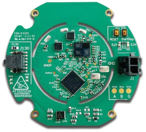
Figure 2. Overview of EPC91122 board – three-phase inverter for drones and humanoid motor joints. Image used courtesy of Bodo’s Power Systems [PDF]
In addition to the existing single-motor reference design board EPC91122, the compact size of the EPC33110 module indeed facilitates the design of multi-axis drivers by enabling dense integration on a small PCB footprint. For instance, four of these modules would compose a quadcopter drone electronic speed controller capable of carrying a payload of a few kilograms on each axis.
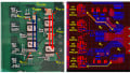
The layout depicted in Figure 3 illustrates a practical example of a 4-axis driver on a 30 mm x 30 mm PCB. Placing a microcontroller centrally allows for efficient routing and control of the four three-phase inverters, while the EPC33110 modules and relative current sensors are placed symmetrically at the four corners of the PCB.
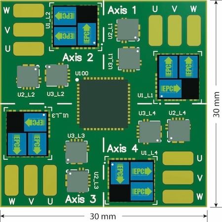
Figure 3. Layout example of a rectangular 30x30 mm multi-axis motor drive, including power stage, current sensors, and microcontroller. Image used courtesy of Bodo’s Power Systems [PDF]
EPC33110 Performance
EPC33110 performance was tested in a humanoid joint motor application with load conditions up to 300 W (20 Nm load torque and 135 rpm motor speed) on a dynamometric bench. Operated at 100 kHz PWM and 25 ns deadtime, the board was able to deliver a repetitive 2-second pulsed phase current of 20 ARMS.
In the case of the motor used in the tests, which had a torque per ampere constant of 1 Nm/ARMS, the 20 Nm maximum load resulted in 20 ARMS, 28 APK current in each leg of the inverter, as shown in Figure 4, at the motor’s maximum speed.
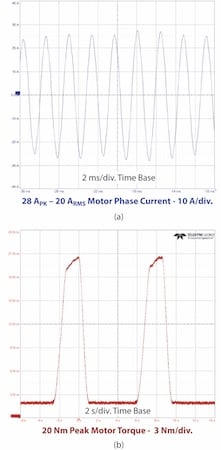
Figure 4. Output current capabilities of EPC33110 operated at 100 kHz PWM in a humanoid robot joint:
(a) detail of the motor phase current reaching 20 ARMS
(b) overview of the load torque 2 second pulses at 20 Nm peak.
Image used courtesy of Bodo’s Power Systems [PDF]
In addition to the dynamometric bench measurements, steady-state measurements on a passive load were performed to identify the maximum current that can be delivered continuously at the thermal regime. The board was tested at 100 kHz with a 25 ns deadtime and a passive heatsink under natural convection cooling.
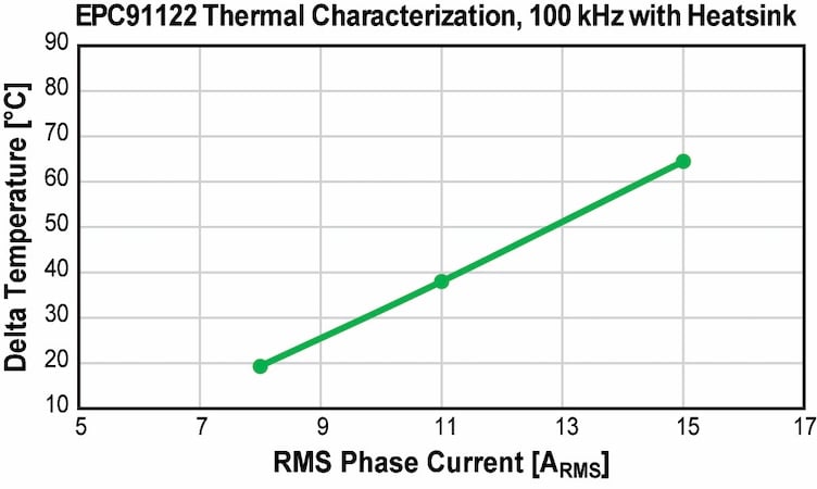
Figure 5. Steady state thermal performance of EPC33110 operated at 100 kHz PWM under natural convection cooling. Image used courtesy of Bodo’s Power Systems [PDF]
The graph represented in Figure 5 reports the results showing that the EPC33110 module reached a temperature increase of 50 °C from ambient temperature while delivering 13 ARMS to each phase of the motor.
While in the case of a humanoid robot, joints natural convection cooling is the only choice, in drone applications, the propellers generate a strong airflow, yielding thrust and effective cooling to the whole system, which increases the inverter current capabilities.
Conclusions
The EPC33110 is a compact three-phase module integrating three GaN half-bridges with built-in gate drivers, bootstrap circuits, and level shifters, optimized for motor control. A single 5 V power supply can power the module to operate up to 80 V with a typical on-resistance of 8.7 mΩ, supporting 3.3 V or 5 V logic inputs.
This simplifies system design by reducing the need for external components. Housed in a 6 x 6.5 mm QFN package with 21 pads, it features complementary PWM inputs, a fast shutdown pin, and power supply pins arranged to minimize PCB resistance and inductance, and enhance thermal dissipation.
The EPC33110 is designed for driving three-phase permanent magnet motors commonly used in drones and humanoid robots. The EPC91122 reference board supports these applications with a wide 15–65 V input range and includes complete motor drive features such as regulated power supplies, DC voltage sensing, magnetic encoder, and current sensors.
The EPC33110, thanks to its compact size and easy layout, also enables multi-axis driver designs which are particularly effective in small drones such as quadcopters with a few kilograms payload or in humanoid robot arms.
Thanks to the top-side cooling optimized by the exposed dies, EPC33110 can deliver up to 20 ARMS per phase, as verified in 2-second pulses in a humanoid joint motor. Operated at 100 kHz PWM and 25 ns dead-time under natural convection cooling, the EPC33110 can deliver 13 ARMS continuously while keeping the temperature increase with respect to ambient temperature below 50 °C and 8 ARMS keeping the temperature increase with respect to ambient temperature below 20 °C; such thermal increase is significantly reduced while operated under forced air cooling conditions, which is typical for aerial drones.
This article originally appeared in Bodo’s Power Systems [PDF] magazine and is co-authored by Federico Unnia, Manager of Applications Engineering, and Marco Palma, Director of Applications Engineering, Efficient Power Conversion