 Facebook
 Google
 GitHub
 Linkedin
Comparing Carrier-Based PWM Techniques in High-Voltage Inverters
This article explores the potential of carrier-based pulse width modulation techniques such as sawtooth, triangular, and sinusoidal, and examines how they directly impact harmonic distortion in high-voltage inverters.
High-voltage inverters form an essential part of renewable energy systems, and these inverters rely on pulse width modulation (PWM) to control the power conversion process. PWM enables precision in wave generation and power quality and provides efficient harmonic suppression. Through the modulation of the width of the voltage pulses, the desired AC waveforms in high-voltage inverters can be approximated for an efficient and smooth power flow to the loads. The shape of the carrier waveform distinguishes different PWM techniques compared to the reference signal. The three major carrier-based PWM techniques include triangular, sinusoidal, and sawtooth. These PWM methods offer a share of advantages and drawbacks in handling harmonic distortion, affecting their suitability in different high-voltage applications, further necessitating the need for comparative analysis to provide better insight into the choice based on the use case.

Image used courtesy of Adobe Stock
Overview of PWM and Harmonic Analysis
By varying the voltage pulse width at a fixed period, PWM controls the voltage delivered to the load. Carrier-based PWM generates switching pulses for the inverter using high-frequency carrier waveforms like sawtooth, sinusoidal, or triangular, comparing them with the reference waveform, which is lower than the modulating signal.

Figure 1. Modulating waveform (Vm) is represented by a sine wave of the desired output voltage, which is compared by the carrier wave (Vc) for the resultant PWM generation (if Vm ≥Vc, PWM output is ON). Image used courtesy of Bob Odhiambo
One of the key parameters considered in carrier-based PWM is the modulation index, which defines the ratio of the modulating waveform’s amplitude (Am) to that of the carrier waveform (Ac). When the modulation index (M) equals or is less than one (linear modulation region), the output voltage waveform closely resembles the reference modulation waveform, which ensures high-quality AC voltage output with minimal distortion. However, when the modulation index is greater than one (overmodulation region), the carrier waveform is exceeded by the reference voltage, increasing the output voltage but at the cost of distortions of the waveform.
\[M = \frac{A_{m}}{A_{c}}\]
Another aspect to consider in PWM is the frequency ratio between the switching frequency (fs) and the output frequency (fo), which must be high enough for a smooth output and shifting harmonics to higher frequencies, easily filtered. The generated PWM signal at a given period (t) can be approximated using the general formula below that compares the desired output waveform (Vm(t)) and the carrier waveform (Vc(t)).
\[V_{PWM}(t)=\,\vdash^{V_{dc}\,\,\,\,\,if\,V_{m}(t)\geq V_{c}(t)}_{0\,\,\,\,\,\,otherwise}\]
Where (Vdc) is the PWM’s high-level voltage.
Analyzing the harmonics produced during the switching operations in carrier-based PWM is essential to understanding the efficiency and performance of high-voltage inverters. Switching-frequency harmonics in PWM signals are often easier to filter using an LC low-pass filter and occur at a higher frequency. High harmonics increase inverter losses, reduce efficiency and lifespan due to overheating, increase electromagnetic interference (EMI), and reduce power quality.
Sawtooth, Triangular, and Sinusoidal PWM Technique
In high-voltage inverters, harmonic distortion control depends on carrier signal selection. In addition to the harmonic filter design for attenuation of specific sideband harmonics, performing an application-based comparison of the three carrier-based PWMs is essential.
In the sawtooth modulation process, the amplitude and frequency of the waveform are some of the major properties that affect the linear rise and sharp drops of the carrier waveform in a repeating pattern. In this case, the modulation index is governed by the waveform's amplitude, while the carrier frequency is affected by the speed at which switching occurs. Regarding asymmetry and harmonic impact, this PWM technique is characterized by increased sideband harmonic content, which results from uneven pulse widths. This and the switching frequency (fs ) significantly affect the output waveform’s quality. Additionally, low-order harmonics from the sharp edges of the carrier signal make filtering difficult due to their prominent nature. Regarding the most suitable application, sawtooth carrier wave works best where the transient response is critical like in high-speed switching applications.
A sinusoidal carrier is characterized by a smooth and continuous waveform that resembles the reference modulating waveform. Before bringing in the modulation concept in sinusoidal PWM, it is essential to look at triangular waveforms to understand how they relate to sinusoidal signals. The triangular waveform rises and falls linearly in one complete cycle to produce a much more balanced switching interval. This results in the concentration of harmonic energy in a predictable frequency, further improving the carrier signal's overall performance by minimizing low-frequency components. Compared to sawtooth PWM, triangular PWM exhibits better harmonic and reduced distortions due to a narrower harmonic distribution. This makes triangular PWM suitable for applications like torque control in motor drives and inverters for renewable energy integrations where smoother outputs and balanced switching patterns are crucial.
In the generation of PWM signals, high-frequency triangular carrier waveform is compared with sinusoidal waveform, in which the points of intersection of the two signals are used to determine the switching instance. One of the major aspects that directly impacts the resultant PWM output is the switching frequency of the triangular carrier. Higher carrier frequency increases switching losses and, on the positive side, increases the resolution of the PWM signal. The sinusoidal variation of the duty cycle of the PWM signal to closely match the reference signal creates a smooth waveform that needs less filtering to produce sinusoidal output. Compared to the other carrier-based PWM techniques, Sinusoidal PWM has the lowest total harmonic distortion (THD), resulting from its accuracy in tracking the reference signal.
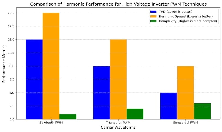
Figure 2. For ease in the selection and identification of trade-offs between complexity and performance, the choice of suitable carrier waveforms for high-voltage inverters can be made based on the insights from the graph. Image used courtesy of Bob Odhiambo
The Results
After a comparative analysis of THD, harmonics spread, and implementation complexity, engineers have better insights to make suitable choices when designing high-voltage inverters.
From this analysis:
- Sinusoidal PWM is the most suitable choice in high-voltage inverters and grid-tied systems due to its minimal THD, efficient harmonic distribution, and waveform quality.
- Triangular PWM offers moderate complexity with a balanced harmonic profile, which is best suited for general-purpose inverters and motor drives.
- Sawtooth’s high harmonic distortion characteristics work best in low-precision applications.


most liekly a typo : “sawtooth PWM has the lowest total harmonic distortion”
I’m afraid your graph as well as your conclusion show the opposite.