Facebook
 Google
 GitHub
 Linkedin
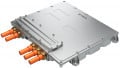
Optimization of GaN-Based Inverters for BLDC Motor Drives
Gallium nitride (GaN) power devices allow an increase in the switching frequency of power converters and a reduction of the dead time; such characteristics can be applied to motor drive inverters with some advantages.
This article is published by EE Power as part of an exclusive digital content partnership with Bodo’s Power Systems.
Recent studies have shown that reducing dead time and increasing switching frequency leads to higher motor efficiency [1].

Image used courtesy of Adobe Stock
A high switching frequency motor drive inverter makes it possible to optimize the capacitance needed for the DC link by requiring only ceramic capacitors, thus reducing the overall converter size. Furthermore, a good layout allows additional removal of the decoupling capacitors close to the switching cells thanks to the low-inductance DC link ceramic capacitors and low-inductance distribution in the layout.
Experimental tests were conducted to prove the previous statements operating a permanent magnet motor using a sensorless field-oriented-control technique.
The GaN motor drive inverters that were tested used both discrete FETs and monolithic integrated circuits, that are made possible by gallium nitride technology.
Effect of Switching Frequency on the DC Link Capacitors
DC link capacitors in a motor drive are primarily used to minimize the fluctuation of the power supply voltage. The two main types of DC link capacitors used in motor drive inverters are electrolytic capacitors and ceramic capacitors. Electrolytic capacitors have a lower cost per capacitance than ceramic capacitors but are larger physically with higher equivalent series resistance and inductance (ESL). Electrolytic capacitors are typically designed based on the RMS ripple current they can carry.
GaN FET-based inverters are operated at higher switching frequencies than silicon MOSFET-based inverters, making it possible to use ceramic capacitors only on the DC bus. Ceramic capacitors are dimensioned based on ripple voltage requirements, which are inversely proportional to the switching frequency of the converter, which proportionally reduces the total capacitance required when increasing the switching frequency. The smaller number of DC link capacitors reduces the total cost and volume of the inverter.

Figure 1. Voltage ripple on DC bus vs. PWM switching frequency for three inverters using ceramic capacitors on the DC link. The voltage ripple at 100 kHz on the 90 µF inverter is slightly lower than the voltage ripple on the 360 µF inverter operated at 20 kHz, showing the benefit of increasing the PWM frequency in motor drive inverters. Image used courtesy of Bodo’s Power Systems [PDF]
Another advantage of ceramic capacitors is their inherent low parasitic inductance (ESL). A good layout and their low ESL make them a low-inductance voltage source, which is a key factor in switching power converters.
The ripple voltage effectiveness of a DC link made of ceramic capacitors is evident when switching at higher PWM frequencies, as presented in Figure 1. This shows the voltage ripple using a 90 µF inverter switching at 100 kHz is lower than the voltage ripple of the inverter with 360 µF capacitance operated at 20 kHz.
Switching Transition Measurements and Switching Cell Optimization
A basic building block of today’s power converters is the switching cell, which is composed of two transistors placed in a cascade across the terminals of a DC bus, making a power loop. Traces on the PCB, vias, and all the connections of the components to the PCB, introduce parasitic inductances in the switching cell.
The power loop inductance can be modeled as the parasitic inductance that is present between the terminals of the switching cell and the DC bus voltage [3]. The power loop is responsible for ringing following hard-switching transitions, which may cause overvoltage across the devices and manifest EMI issues. The most common method used to minimize the power loop inductance is to place decoupling ceramic capacitors electrically close to the transistors of each switching cell.
In motor drive applications, the switching transition slew rate is intentionally kept low typically with dv/dt below 10 V/ns. Slow transitions generate less ringing and require fewer decoupling capacitors close to the switching cell than for higher slew rate transitions. With a good PCB layout, DC link ceramic capacitors can provide a low inductance connection to the switching cell.
As an experimental evaluation, two EPC’s motor drive inverter boards were tested; the EPC9145 [4] uses discrete EPC2206 [5] GaN FETs, and the EPC9173 [6] that uses the EPC23101 [7] monolithically integrated gate driver and FET GaN IC.
The EPC9145 motor drive inverter was equipped with a bulk DC link comprising ceramic capacitors and two local to the switching cell decoupling capacitors also comprised of ceramic capacitors. The first board was equipped with 9x 220 nF high-frequency loop decoupling capacitors and 16x 1 µF middle-frequency decoupling capacitors, whereas the second board was devoid of decoupling capacitors and operated solely using the bulk DC bus capacitors.
The inverter was operated at 100 kHz switching frequency and was driving a permanent magnet motor with field-oriented control with a 50 A peak sinusoidal current.
The waveforms in Figure 2 show the rising and falling transition measured at 50 A positive and negative phase currents. With the decoupling capacitors removed, the difference in rising transition was considered small with very little degradation to the inverter operation. The falling transition difference was close to negligible. In the case of the inverter equipped with no decoupling capacitors, the overshoot never exceeded 25% of the bus voltage.

Figure 2. Waveforms showing the rising and falling transition measured at 50 A positive and negative phase current of inverter operated at 100 kHz driving a permanent magnet motor. The blue waveform is the inverter equipped with many decoupling capacitors. The red waveform is the inverter operated without any decoupling capacitors. Image used courtesy of Bodo’s Power Systems [PDF]
The same experiment was performed using the EPC9173 GaN IC-based motor drive inverter. The monolithic GaN power IC integrates the gate driver and the power FETs onto the same chip effectively eliminating common-source inductance (CSI) [3] and simplifying the layout of the switching cell with and keeping the parasitic loop inductances to a minimum.
The waveforms of the switching transition measured on the integrated circuit-based inverter at positive and negative 50 A peak currents are reported in Figure 3.

Figure 3. Waveforms of the switching transition were measured on the integrated circuit-based inverter at positive and negative 50 A peak current. The blue waveform is the inverter equipped with many decoupling capacitors. The red waveform is the inverter operated without any decoupling capacitors. Image used courtesy of Bodo’s Power Systems [PDF]
The monolithic integrated GaN Power IC minimizes the commonsource parasitic inductance present in the half-bridge switching cell thus reducing the need for external decoupling capacitors, including over discrete GaN FET based inverters.
Effect of Capacitor Type on Switching Node Transition
Ceramic capacitors for the DC link can yield a low-inductance connection to the switch converter cells across the PCB when the planes are interleaved to cancel return current magnetic flux, cover a large area, and apply vias close to the inner connections of the capacitor.
An experiment was conducted between two GaN FET inverters, fitted with different DC link capacitor types. The first inverter was equipped with 2x 47 µF SMD electrolytic capacitors and no decoupling capacitors on the switching cells. The second inverter was equipped with 9x 10 µF multilayer ceramic capacitors. The choice of capacitor values was chosen to yield a similar nominal DC bus capacitance.
Figure 4 shows the measured waveforms of the rising transition of each of the two inverters operating at 50 A peak positive and negative phase currents. The inverter equipped with ceramic capacitors exhibits little voltage overshoot and ringing that decays within 50 ns. The inverter equipped with electrolytic capacitors experiences significant voltage overshoot and ringing that lasts several hundred nanoseconds.

Figure 4. Measured waveforms of the rising transition of inverters using 90 µF DC bus ceramic and electrolytic capacitors operating at 50 A peak positive and negative phase current. Image used courtesy of Bodo’s Power Systems [PDF]
Based on the experiments conducted, it is clear that electrolytic capacitors are not a good choice for GaN FET- and IC-based motor drive inverters when attempting to eliminate the ceramic decoupling capacitors for the switching cell. The electrolytic capacitors used in the experiments were low-ESL and low-ESR capacitors and were still insufficient for the application.
Takeaways of GaN FETs and ICs
GaN FETs and ICs can be used effectively to design optimized and efficient motor drive inverters.
Due to the superior switching performance of GaN devices, inverters utilizing these devices can be optimized by reducing the number of components, thus reducing the overall volume of the inverter over lower frequency MOSFET-based inverters. Switching at a higher frequency allows for the use of ceramic-only capacitors for the DC link, which not only reduces the volume of the input filter but opens the option of removing the high-frequency decoupling capacitors on the switching cell.
An optimized motor drive GaN inverter with 90 µF DC link ceramic capacitors and without any decoupling capacitors operated at 100 kHz can smoothly drive a permanent magnet motor with a 50 A peak sinusoidal phase current.
References
[1] S. Musumeci, F. Mandrile, V. Barba, and M. Palma, “Low-Voltage GaN FETs in Motor Control Application; Issues and Advantages: A Review.” In Energies 2021, 14, 6378.
[2] A. Lidow, Ed. GaN Power Devices and Applications, El Segundo, CA, USA: Power Conversion Publication, 2022, First Edition, ISBN: 978-0996649223.
[3] A. Lidow, M. de Rooij, J. Strydom, D. Reusch, J. Glaser, GaN Transistors for Efficient Power Conversion, Third Edition, Wiley, ISBN 978-1-119-59414-7.
[4] EPC9145 KIT – 1 kW 3-phase BLDC Motor Drive Inverter Evaluation Board (epc-co.com) https://epc-co.com/epc/products/demo-boards/epc9145
[5] EPC2206: Automotive 80 V Enhancement-Mode GaN Power Transistor | EPC (epc-co.com) https://epc-co.com/epc/products/gan-fets-and-ics/epc2206
[6] EPC9173 35 ARMS 3-Phase BLDC Motor Drive Reference Design Board (epc-co.com) https://epc-co.com/epc/products/demo-boards/epc9173
[7] EPC23101: 100 V, 65 A ePower Chipset (epc-co.com) https://epc-co.com/epc/products/gan-fets-and-ics/epc23101
This article originally appeared in Bodo’s Power Systems [PDF] magazine.