Facebook
 Google
 GitHub
 Linkedin
Value Enhancement of Full SiC 3.3kV Power Module
This article focuses on the 2-level inverter and use this topology to exhibit the results
Hitachi has been at the forefront of introducing new packaging technology for high power semiconductors. Implementing the next generation package platform, nHPD2, the product line-up of full SiC 3.3 kV modules is being expanded. By providing SiC Schottky barrier diode (SBD) co-packaged with SiC MOSFETs and full SiC chopper modules applicable circuit configurations such as 3 level converters, brake chopper circuit, and boost converter can be implemented.
Hitachi is introducing Copper sintering technology to the full SiC nHPD2, which replaces the conventional soldering thus elevating the maximum operating junction temperature Tvj(op). This drastically improves the power cycle durability. We have shown the maximum available output current which has been estimated using the mission profile of a METRO traction motor inverter. The performance of the full SiC 3.3 kV power module without SBD is revealed to enhance power cycling by 6 times that of a conventional Silicon counterpart in the same package platform. Presented here are the performance benefits obtained from these technology introductions.
For traction converter systems, high power density is a key parameter for driving towards reducing size and weight. Silicon carbide (SiC) power modules are inherently suited to achieve the above goals due to low loss, faster-switching speed and high-temperature characteristics as compared to their Silicon (Si) counterpart. However, the advantage of high switching speeds can be compromised by the switching oscillations leading to lower switching speeds in real-time applications.
Apart from reducing the switching speeds which negate the inherent advantage of SiC we can also aim to reduce stray inductances at the power module level. This can have a significant impact on reducing switching oscillations for the motor control systems thus enabling systems to avail the advantages of SiC technology. Young’s modulus characteristics of SiC also stifle the appetite to transition to WBG technologies in high-reliability applications.
Package Platform for SiC
In 2015, Hitachi presented a next-generation low-inductance package for high-voltage and high-current/power devices named “next High Power Density Dual (nHPD2)” [1]. This package was developed to extract the best performance from high-voltage wide band-gap semiconductor devices, which have significantly faster switching speeds than that of their Si devices. To achieve this goal, the first step required is to reduce the total loop inductance by a significant magnitude.
This can be realized by aligning the conduction paths inside and outside of the package as anti-parallel and securing sufficient insulation distances. This enables us to estimate the product of the total inductance, including the filter capacitance and the rated current product, which is as low as 40 nH * 450 A (18 μA•H). The inductance was verified as being low enough for SiC devices in high-voltage, high-power applications to provide superior switching characteristics without generating oscillations [2, 3].
Figure 1 shows a comparison between the conventional high-voltage package platform and nHPD2 and between the Si-IGBT + SFD (soft and fast recovery diode) and Si + SiC-SBD. In this example, by using the SiC-SBD for Si SFD, reverse recovery energy became one-hundredth of the original value, and the turn-off oscillations were completely reduced. In addition to these effects, the turn-ON and turn-OFF energy could be reduced significantly.

Figure 1: Comparison between the conventional high-voltage package platform and nHPD2 for different semiconductor configuration
Based on the presented research the scope of this study was expanded to SiC-MOSFETs. To enable characterization, we populated 3.3 kV SiC MOSFETs and anti-parallel SiC-SBDs in a nHPD2 package. Results exhibiting low switching energy and smooth switching waveforms were presented here earlier [4]. Figure 2 shows the simulated dependence of the maximum output current on the carrier frequency for the PWM inverter operation under similar cooling conditions for 3 variants of nHPD2 package. The 3 variants under discussion include the latest Si-IGBT + Si-SFD (Si+Si), latest Si-IGBT + SiC-SBD (Hybrid), and SiC-MOSFET + SiC-SBD (Full-SiCwSBD).
The operation of a traction motor inverter for both acceleration and deceleration with power factors of +98 % (solid line) and -98 % (dotted line) corresponding to each state, respectively, was assumed. In the case of Si+Si, the maximum available output current decreases considerably with increasing carrier frequency due to the comparably larger switching energy loss. In contrast, Hybrid and Full-SiCwSBD have a moderate decrease in the maximum available output current. However, when Hybrid operates at low frequency and with a negative power factor (PF = -98 %, fc < 500 Hz) and when Full-SiCwSBD operates at low frequency with a positive power factor (PF = 98 %, fc < 200 Hz), the maximum available output currents are even lower than those of Si+Si power module configuration.
It was also observed that Hybrid exhibits almost negligible reverse recovery energy (Err), and conversely, the VF of SiC SBD is much higher, especially at a high current density. In case of Full-SiCwSBD, the reverse current is shared between the SiC SBD and the positive-gate-biased MOSFET. It is expected that the voltage drop, VDS(on) of a MOS structure is higher than that of an IGBT at higher current densities which will have an impact on higher conduction losses. Furthermore, except for unidirectional converters, such as an auxiliary inverter, most of the traction inverters are bidirectional, and they are expected to have the same output current in both directions. Therefore, the rated outputs are limited by the lower output of the plotted curve for the Full-SiCwSBD.

Figure 2: Comparison of the dependence of maximum output current on the carrier frequency
Full SiC Without SiC SBD
In the 1st-generation nHPD2 full-SiC module, the SBD was used to remove the risk of bipolar degradation in the MOS structure. Hitachi has been actively involved in analyzing and demonstrating the mechanism for bipolar degradation caused by stacking faults (SFs) generating from basal plane dislocations (BPDs). Subsequently, we have successfully proposed solutions to overcome these phenomena [5, 6]. The adoption of this technology solution enables the realization of high-voltage full SiC without SBD (Full-SiCw/oD), which does not show bipolar degradation and possesses sufficiently high gate oxide reliability [7, 8]. Figure 3 details the mechanism for bipolar degradation and an example of a degraded SiC-MOS. Triangle-shaped SFs are observed, and the electron current paths are supposed to be blocked by SFs. This behavior causes an increase in VDS(on) from its initial value as the device ages. Figure 4 provides a test flowchart to eliminate the chips that have the potential to reveal bipolar degradation during field operation. The degradation quantity is evaluated by ΔVon, which is the difference in the forward on-voltage before and after the current conduction through the body diode over time [8]. Using this methodology, Hitachi has realized a 3.3 kV full SiC by eliminating the SBD, and thus enabling us to expand the active area of SiC MOSFETs. Increasing the active area has a direct correlation with the rated current which can be increased to as high as 800 A, versus the 1st-generation 450 A, using the same package platform of nHPD2 [7].
However, the presence of SiC SBD represents great advantages in other circuit configurations. Hitachi has added two chopper configurations: P-type (MSL800FS33PLT), with the MOSFET at the top arm and the SBD at the bottom arm, and N-type (MSL800FS33NLT) with the opposite arrangement [9], in addition to the dual configuration. These full-SiC chopper modules are aimed to apply in several circuit topologies such as a 3-level converter, break chopper and boost converter as detailed in Figure 5. Just to clarify it should be mentioned that the red part in Figure 5 represents MSL800FS33PLT, and the blue part shows MSL800FS33NLT. In this article, we intend to focus on the 2-level inverter and use this topology to exhibit the results.
![Figure 3: Bipolar operation in SiC may cause SF expansion from BPDs [7]](https://eepower.com/uploads/articles/Fig3_Value_Enhancement_of_Full_SiC_3.3kV_Power_Module_in_nHPD2_Package_.jpg)
Figure 3: Bipolar operation in SiC may cause SF expansion from BPDs [7]

Figure 4: Sequence of bipolar degradation screening process for SiC MOSFETs
Figure 5: Example applications of the full SiC chopper module. Red: MSL800FS33PLT, Blue: MSL800FS33NLT. (a) one phase of a 3-level converter, (b) a break chopper in a 2-level traction converter, and (c) a boost converter
How Copper Sintering Enhances Output Current
Copper (Cu) possesses a substantially higher melting point than that of conventional solder materials. By introducing Cu as a bonding material, the Tvj(op) of 3.3 kV devices can be enhanced, from the current 150°C, to 175°C, and this enhancement enables a 25 % higher maximum available current (rated 1000 A) [10]. As shown in Table 1, the material properties of conventional solder, Silver (Ag), and Cu are compared. Ag and Cu are used as sintering materials, not only for their melting points but also for the values of their thermal conductivity and yield stress, which are considerably greater than those of conventional solder. From a cost perspective, Cu sintering is more viable than Ag sintering.
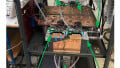
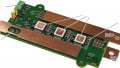
For semiconductor metallization purposes, we get more effective bonding from Cu sintering. Moreover, the pressure force required for Cu sintering is significantly less than that for Ag sintering. Taking all these advantages into account Cu sintering is expected to enhance the product value substantially more than the corresponding increase in product cost with Ag sintering. Figure 6 shows cross-sectional scanning electron microscopy (SEM) images for different layers.
The data confirm that metalized SiC and the Cu electrode on the insulating substrate are bonded properly by Cu sintering. Figure 7 shows switching waveforms rated at 1000 A, 175°C for the nHPD2 package platform, which is named MSM1000GS33ALT—where “S” indicates full SiC, and “G” indicates Cu sintering. Despite more than double the rated current as shown in Figure 7 (d) for the rated package platform, smooth waveforms and low switching losses are confirmed.
Table 1: Comparison of material properties of conventional solder, Ag sintering, and Cu sintering.
| Conventional Solder | Sintered Silver | Sintered Copper | |
| Thermal conductivity (W/(m.k)) | 24 | 427 | 398 |
| Melting point (ºC) | 280 | 962 | 1085 |
| CTE (ppm/K) | 17 | 19.7 | 16.6 |
| Yield stress (MPa) | 59 | 262 | 310 |
| Electrode material to be bonded | Cu,Ni | Ag,Au | Cu,Ni |
| Material cost | Low | High | Low |

Figure 6: Cross-sectional SEM images of the Cu sintering layer.

Figure 7: Switching waveforms of MSM1000GS33ALT. (a) turn-ON, (b) turn-OFF, (c) reverse recovery, (d) RBSOA, (e) Short circuit (Type 1).
In order to evaluate the output current from the inverter operation environment, we repeated the simulation as shown in Figure 2 for Full-SiCw/oD with conventional solder (MSM800FS33ALT) and Cu-sintered Full-SiCw/oD (MSM1000GS33ALT). The results are overlayed on the same plot as shown in Figure 2 in order to have a direct comparison as seen in Figure 8. Unlike Hybrid or Full-SiCwSBD, the maximum available output current for positive and negative are overlapped, and the simulated output currents can be fully achieved in the rated current. The maximum available output current of MSM1000GS33ALT is 2.3 times that of Si+Si configuration at a carrier frequency of 1000 Hz, which increases to about 4 times at 2000 Hz. These increased performance gains are considerably higher than the ones we achieve using the state of art standard product.

Figure 8: Full SiC w/o SBD with conventional solder and with Cu sintering added on Figure 2.
Product Value in Considering Product Lifetime for a Traction Converter
The discussion up to now has assumed that the maximum available current is defined at the maximum junction temperature while including a reasonable safety margin (here, 15K was used). However, when the actual maximum current is defined in the field operation, the temperature cycling during actual operation must be taken into consideration. SiC is a hard material, which exhibits a Young’s modulus thrice that of Si. Therefore, for the power cycle test under same ΔTj and Tj(max) conditions, it was reported that SiC devices show only


Figure 9: Lifetime estimation flowchart for the mission profile analysis.
one-third of the durability of Si devices [11, 12]. On the other hand, SiC devices with Cu sintering present a power cycle durability 20 times that of the same semiconductor devices with conventional solder [12]. Considering these effects in addition to the effects of total loss reduction by using SiC, the following discussion will reveal the real values of each technology in an actual inverter operation. Herein, as an example, we used the mission profile of METRO, and the output current at which the estimated product lifetime reaches the defined period (30 years, F=1 %).
Figure 9 shows a flowchart of the mission profile analysis. Input data are (a) the inverter operation pattern (output current, voltage of the filter capacitor, and carrier frequency), and (b) the loss curve with temperature dependence (from the product data-sheet). Based on the input data we arrive at (c) The transient power dissipation. From (c) and (d), the thermal impedance curve, junction temperature, and case temperature can be estimated as shown in (e). Then, (e) is feedbacked into (c) the power dissipation calculation. The temperature swing for the whole mission profile can be calculated (e). Using the Rainflow method, the parameters used in the lifetime calculation such as ΔTj, Tj(max), and a ton can be derived. Based on the parameters derived we use the linear damage rule and modified Coffin-Manson rule, to estimate the lifetime.

Figure 10: Dependence of the estimated lifetimes of the METRO mission profile on the maximum output current.
Si-IGBT (MBM450FS33F), Full-SiCw/oD (MSM800FS33ALT), Full SiC w/o SBD with Cu sintered (MSM1000GS33ALT).
Figure 10 shows the dependence of the estimated lifetime for the METRO mission profile on the maximum output current for Si+Si (MBM450FS33F), Full-SiCw/oD (MSM800FS33ALT), Full-SiCw/oD Cu-sintered (MSM1000GS33ALT). As there is an increase in output current, the power dissipation from the power module increases (ΔTj, ΔTc, Tj(max), and Tc(max) increase). Consequently, the estimated lifetime decreases. Therefore, the relations become as shown by the lower-right curves. In the case of Si+Si (MBM450FS33F) at 660Hz maximum, increasing the output current by 1.33 times, the estimated lifetime decreases to one-fourth the value as highlighted by label (①).
From another perspective, we can safely assume that if by increasing the lifetime 4 times, the product value enhances to 1.33 times. Replacing Si with SiC, we can increase the maximum output current from 300 A rms to 480 Arms for a lifetime of 10 years at 1% failure as pointed by label (②). This increase (approx. 1.6) achieved in maximum output current values represent the same ratio as that of the rated current increase achieved (450 A to 800 A which 1.7).
Furthermore, by adopting Cu sintering, the power cycle test results show a durability 20 times that achieved with conventional solder. According to the mission profile analysis, the lower Tj(max) dependence and t on dependence result in a significantly higher operation lifetime of 40 times marked by label ③. Comparing SiC with conventional solder and with Cu sintering for 10 years with a 1 % failure rate, the maximum output current increases from 480 Arms to 680 Arms as shown by label ④. This increased ratio is 1.4, which is substantially higher than the ratio of the rated currents determined from the results of the output current estimation limited by the Tj(max) which was observed to be about 1.3.
Increasing the carrier frequency makes it possible to reduce the motor current ripple, which results in a reduction in the total loss from the motor and inverter [13]. Case studies increasing the carrier frequency by 3 times are shown with dotted curves in Figure 10 (a), and the dependences of the maximum available output current fulfilling 10 years at 1% failure on carrier frequency are shown in Figure 10 (b).
It can be clearly seen that Si+Si configuration shows a drastic decrease of 60% at a 3 times-higher carrier frequency for maximum output current; however, Full-SiCw/oD decreases by only 25%. The current rating capability for the same product at a 3 times-higher carrier frequency is as high as a factor of 6 times. We aim to have the samples available soon for the SiC version of nHPD2 with Cu sintering.
Summary
Enabling lifetime enhancement has been a lifetime’s challenge for rail traction inverters. HITACHI’s development in this application area has always been to be at the forefront to challenge existing boundaries. Keeping the vision alive we have presented our next generation of low inductance package with SiC technology. In order to take full advantage of wide bandgap technology ensuring a low inductance power module package is essential. We have highlighted the benefits of this package in SiC technology. While demonstrating the power rating enhancement of nHPD2 package in SiC technology we have also exhibited significant lifetime improvements by introducing Cu sintering. Results presented here showed an improved lifetime of 40 times for the same output current with Cu sintering.
About the Author
Katsuaki Saito works for Hitachi Power Semiconductor Devices. Saito's focus is in power devices, high power IGBT, diode and thyristors.
References
- D. Kawase, et al., “High voltage module with low internal inductance for next chip generation - next high power density dual (nHPD2),” PCIM Europe 2015.
- K. Saito, et al. “Suppression of reverse recovery ringing 3.3kV/450A Si/SiC hybrid in low internal inductance package: next high power density dual; nHPD2,” APEC 2016.
- K. Saito, et al., "Simplified model analysis of self-excited oscillation and its suppression in a high-voltage common package for Si-IGBT and SiCMOS," IEEE TED, vol. 65, no. 3, (2018)
- T. Ishigaki, et al., “3.3kV/450A full-SiC nHPD2 (next high power density dual) with smooth switching,” PCIM Europe 2017.
- A. Shima, et al., ” 3.3 kV 4H-SiC DMOSFET with Highly Reliable Gate Insulator and Body Diode,” ECSCRM 2016.
- K. Konishi, et al., ” Modeling of Stacking Fault Expansion Velocity of Body Diodes in 4H-SiC MOSFET,” ECSCRM 2016.
- T. Ishigaki, et al., “A. 3.3kV/800A Ultra-high power density SiC power module,” in PCIM Europe 2018.
- T. Ishigaki et al., “Analysis of Degradation Phenomena in Bipolar Degradation Screening Process for SiC-MOSFETs”, ISPSD 2019.
- Hitachi Power Semiconductor Device Ltd. SiC(Full SiC) [Online]. Available: http://www.hitachi-power-semiconductor-device.co.jp/en/products/igbt/sic/ index.html
- K. Yasui et al.,” A 3.3 kV 1000 A High Power Density SiC Power Module with Sintered Copper Die Attach Technology.” PCIM Europe 2019.
- J. Lutz, “Packaging and Reliability of Power Modules”, CIPS 2014.
- K. Yasui, et al “Improvement of power cycling reliability of 3.3kV full-SiC Power modules with sintered copper technology for Tj,max=175°C”, ISPSD 2018.
- A. Blomberg, “Stockholm Metro SiC demonstration project – Results”, [Online]. Available: https://www.acreo.se/sites/default/files/pub/acreo.se/Events/SCAPE_2018_ Presentations/Workshop/Day_1/13_anders_blomberg_bombardier.pdf
This article originally appeared in the Bodo’s Power Systems magazine.