Facebook
 Google
 GitHub
 Linkedin
Meeting Compact Inverter Design Demand With Small Size While Maintaining Insulation Distance
In recent years, power density of a power inverter stages are increasing by providing low power losses as well as compact size so that the demand of environmentally friendly, efficient, and light inverter stages could be designed. To meet the challenges of these small and light inverter design, COMPACT DIPIPM have been developed in a smaller package still maintaining the insulation distance compared to conventional products.
Article co-authored by Keisuke Kawamoto, Mitsubishi Electric Europe, Germany and Akiko Goto, Mitsubishi Electric, Japan.
This article is published by EEPower as part of an exclusive digital content partnership with Bodo’s Power Systems.
Back in 1997, Mitsubishi Electric introduced the very first DIPIPM Concept in the power electronic industry, which integrated power semiconductors (3 phase inverter stage with IGBT and FWD), LVIC (Low Voltage Integrated circuit) and HVIC (High Voltage Integrated Circuit) gate drivers with protection logic circuits for cost-effective inverter applications [1]. Since then, development of different types of DIPIPM Families with 600V and 1200V rating for various output current ratings and additional topologies has continued [2]. Main target of DIPIPM development has always been to increase power density of a power stage by providing DIPIPM with low power losses as well as compact size so that the demand of environmental friendly, efficient, and light inverter stages could be designed [3].
A new Family of COMPACT DIPIPM Series with current/voltage rating of 30A-50A / 600V, which have recently been introduced to the power electronics industry to mainly address PAC (Package Air Conditioner), Heat Pump Compressor Drive, and motor drives for industrial machines, maintain same isolation voltage (2500Vrms/1min) as Mini DIPIPM Family whilst reducing the package size requirement 43% , hence it is able to cover a wide range of inverter output power capacity with small package size and lower cost. COMPACT DIPIPM incorporates, 6 pieces of RC-IGBT, 1 piece of HVIC, 1 piece of LVIC and 3pieces of BSD (Bootstrap Diodes) [4].
Internal Schematic and Package Concept of COMPACT DIPIPM
In order to reduce the size and cost, COMPACT DIPIPM has been implemented with RC-IGBT technology, which integrates an IGBT and an FWD (Free Wheeling Diode) in a single chip. HVIC and LVIC incorporated in the package are not only responsible for driving the power switches but are also used protection and feedback such as UV (Under Voltage), SC (Short Circuit implemented only for low sides), VOT (Analogue Temperature Output), interlock circuit to prevent short circuit between P-N arms, and Fo Output (activated only for low side UV and SC protection). Integrated Bootstrap diodes allow the operation of the device with a single 15V power supply.
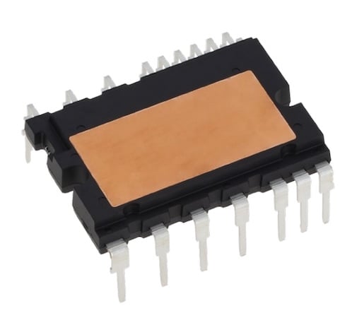
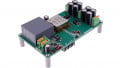
Figure 1. Outline of COMPACT DIPIPM. Image used courtesy of Bodo’s Power Systems [PDF]
Outline, Internal Schematic and Internal Cross-Section Structure of COMPACT DIPIPM are illustrated in Figure 1, Figure 2 and Figure 3 respectively.
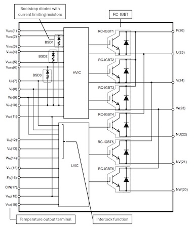
Figure 2. Internal schematic. Image used courtesy of Bodo’s Power Systems [PDF]
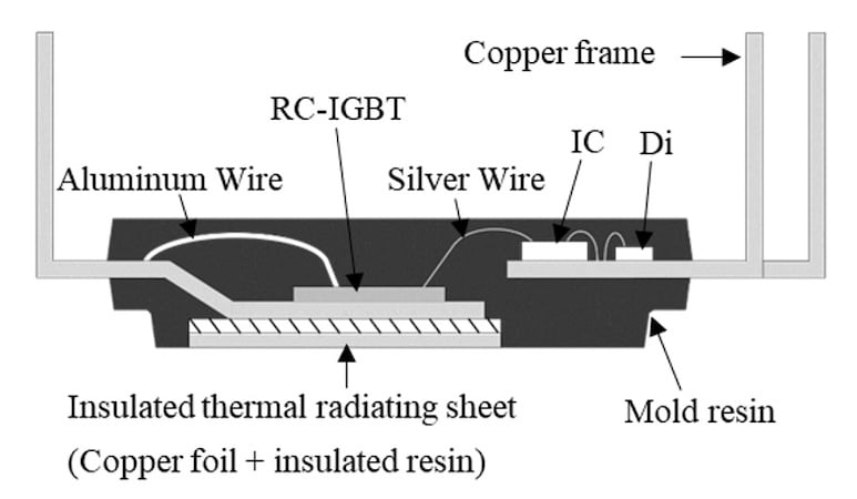
Figure 3. Internal cross-section structure. Image used courtesy of Bodo’s Power Systems [PDF]
Features of COMPACT DIPIPM
Reduction of the Package size
COMPACT DIPIPM has been implemented with RC-IGBT technology that integrates an IGBT and an FWD in a single chip so that the total number of power chips could be halved (Figure 4). Compared with Mitsubishi Electric Mini DIPIPM, which is the conventional DIPIPM of Mitsubishi Electric with voltage ratings of 600V and 1200V, COMPACT DIPIPM needs only 43% less package size to deliver the same current level at the same voltage ratings, as shown in Figure 5.
Even though the package size of COMPACT DIPIPM has been reduced, the design of the package with deep step cross-sectional structure between the heat dissipation surface and terminals ensures the creepage (4mm) and clearance (3.2mm) typical distance so that same isolation voltage (2500Vrms/1min) as of Mini DIPPM could be maintained (Figure 6).
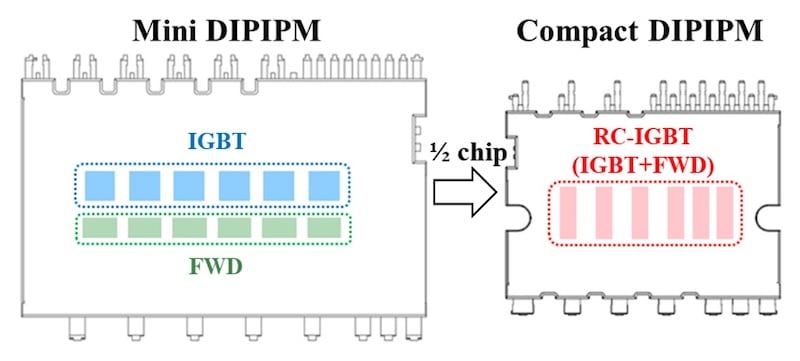
Figure 4. Chip layout comparison. Image used courtesy of Bodo’s Power Systems [PDF]
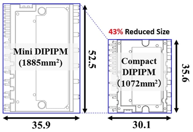
Figure 5. Package size comparison. Image used courtesy of Bodo’s Power Systems [PDF]
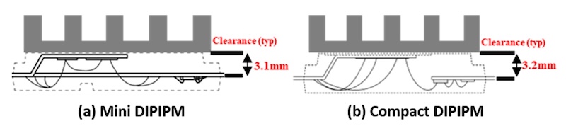
Figure 6. Typical distance from terminals to heat sink. Image used courtesy of Bodo’s Power Systems [PDF]
Simplified Layout Pattern
Mini DIPIPM, which contains 3pieces of HVICs to drive each P-side power switches individually, needs individual wiring of power supply pattern for each of high side. On the other hand, state-of the-art HVIC design of COMPACT DIPIPM covers all of P-side driver stages in single element so that the pattern wiring of the high side power supply could be simplified. Thus, BSC circuit design is further simplified and enhanced without having the control power supply terminals, GND terminals as well as the input signal terminals cross each other as illustrated in Figure 7.
Reduction of Thermal Resistance
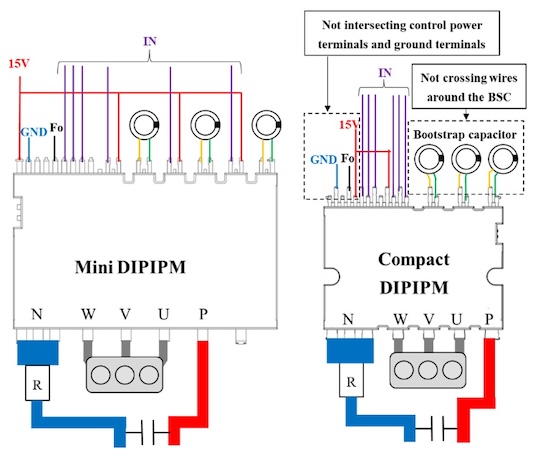
Figure 7. PCB layout. Image used courtesy of Bodo’s Power Systems [PDF]
COMPACT DIPIPM integrates the 3rd generation RC-IGBT (3rd RC-IGBT). IGBT and diode portions of an RC-IGBT mutually dissipates the heat so that power density could be increased whilst the thermal resistance decreases [5][6]. Diode layout of 2nd generation RC-IGBT (2nd RC-IGBT) and 3rd RC-IGBT have been illustrated. In 3rd RC-IGBT, the heat dissipation could be improved by two aspects compared with 2nd RC-IGBT which are i. arrangement of diodes more densely in an island pattern, ii. increased boundary length between the IGBT and the diode (Figure 8).
Reduction of thermal resistance is not only limited to chip level improvement but also due to the insulation sheet structure used in COMPACT DIPIPM which has about 70% higher thermal conductivity compared with that of Mini DIPIPM insulation sheet.
Additional Functionalities
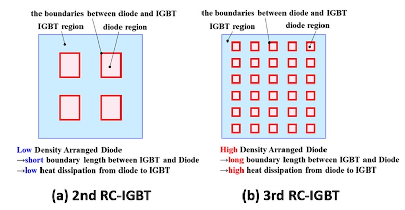
Figure 8. Diodes arrangement on RC-IGBT. Image used courtesy of Bodo’s Power Systems [PDF]
COMPACT DIPIPM comes with BSD functionality and VOT function of monitoring LVIC temperature which could be used for generating control supply for high sides from a single 15V power supply and for enabling control system to monitor LVIC temperature to set-up over temperature protection, respectively.
Moreover, integrated interlock function contributes to safe operation of the system by preventing simultaneous turn-on of both P and N sides by turning off the corresponding N-side without outputting Fo signal (Figure 9).
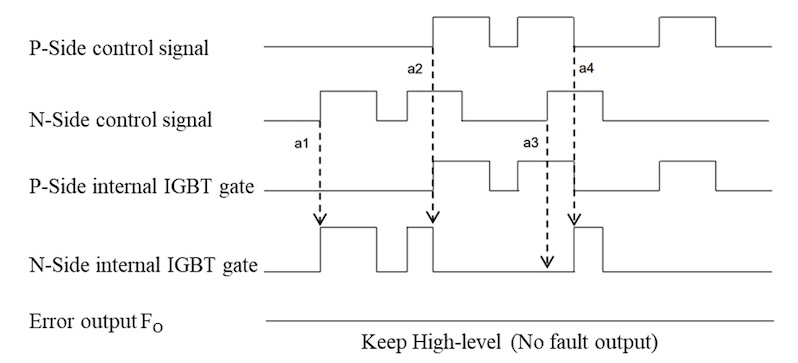
Figure 9. Timing chart of interlock function. Image used courtesy of Bodo’s Power Systems [PDF]
Electrical Characteristics
Turn-on and Turn-off waveforms of COMPACT DIPIPM have been illustrated in Figure 10 and Figure 11 respectively. As can be seen from the figures, during turn-on, no oscillation has been observed whereas during turn-off the tail current falls smoothly in a fast fashion.
In the meantime, loss simulations of 50A COMPACT DIPIPM (PSS50SF1F6) and 50A Mini DIPIPM with BSD (PSS50S71F6) were conducted with following conditions, modulation method SVPWM, Vcc=390V, IO=25Arms, PF=0.97, M=1, fc=6.6kHz, fo=60Hz, VD=VDB=15V. As shown in Figure 12, the total loss of COMPACT DIPIPM could be reduced by 8.5% compared with that of Mini DIPIPM with BSD by reducing the package size whilst thinning the chip and optimizing the driving capacity.
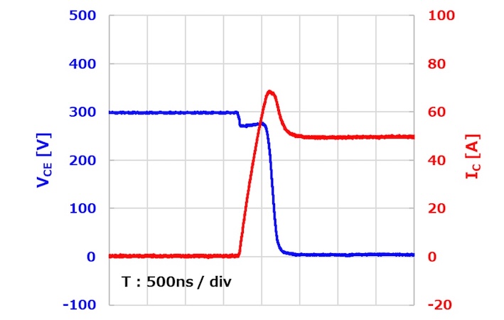
Figure 10. Compact DIPIPM turn-on waveform. Image used courtesy of Bodo’s Power Systems [PDF]
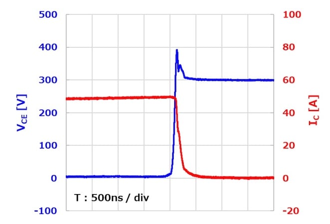
Figure 11. COMPACT DIPIPM turn-off waveform. Image used courtesy of Bodo’s Power Systems [PDF]
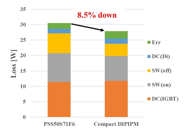
Figure 12. Loss simulation result. Image used courtesy of Bodo’s Power Systems [PDF]
Conditions: SVPWM, Vcc=390V, Io=25Arms, PF=0.97, M=1, fc=6.6kHz, fo=60Hz, VD=VDB=15V
Conclusion
COMPACT DIPIPM, embedding RC-IGBT technology, allows smaller package implementation and lower or similar level of power losses compared with that of previous generation Mini DIPIPM Series, while simplifying board layout design by providing optimal pin placement. COMPACT DIPIPM is the perfect DIPIPM match for compact power inverter stage design of PAC and low power industrial drives.
* SLIMDIP and DIPIPM are trademarks of MITSUBISHI ELECTRIC CORPORATION.
References
[1] S. Noda, K. H. Hussein, S. Yamada, G. Majumdar, T. Yamada, E. Thal and G. Debled, “A Novel Super Compact Intelligent Power Module,” International Power Conversion Conference (PCIM), Germany, 1997.
[2] A. Goto, E. Wiesner, E. Stumpf and N. Soltau, “The DIPIPM Family: Our Technology, Your Comfort”, Bodo’s Power, Sep. 2023, pp. 18-26
[3] T. Takao, K. Kawamoto, H. Murakami, K. Takakura, M. C. Ozkilic, A. Goto and K. Noguchi, “Parallel Operating SiC MOSFET and Si RC-IGBT in SLIMDIP for Higher Efficiency Air Conditioners”, International Exhibition and Conference for Power Electronics, Intelligent Motion, Renewable Energy and Energy Management, Nuremberg, Germany, 2025
[4] T. Miyazaki, N. Ikeda, S. Yokoyama, H. Nakamura, M. Shiramizu and H. Huang, “New Transfer-Molded COMPACT DIPIPM”, International Exhibition and Conference for Power Electronics, Intelligent Motion, Renewable Energy and Energy Management, PCIM Asia Shanghai Conference 2025, China, 2025
[5] S. Soneda, K. Konishi, K. Suzuki, K. Sakaguchi, A. Furukawa, “3rd Gen. RC-IGBT Technology Contributing to a Decarbonized Society”, IEEJ Transactions on Electronics, Information and Systems, Vlo.144 NO.3 pp.228-233(2024)
[6] K. Sakaguchi, K. Konishi, K. Eguchi, and S. Soneda : “Reduction of Junction Temperature with Local Lifetime Control and High Density Arranged Diode for 3rd Gen. 650V RC-IGBT”, Proc. ISPSD2023, pp. 215-218 (2023)
This article originally appeared in Bodo’s Power Systems [PDF] magazine and is co-authored by Dr. Mustafa Cem Ozkilic, and Keisuke Kawamoto, Mitsubishi Electric Europe B.V., and Akiko Goto, Mitsubishi Electric Corporation, Fukuoka, Japan