Facebook
 Google
 GitHub
 Linkedin
Improving DC/DC Converter Design With SiC Power Modules
Power-electronic-converter developers continuously strive for higher converter power densities at the highest efficiency. This has become even more important considering the common goals for reducing CO2 emissions and the responsible use of electric energy and materials. To achieve further improvements, especially in the DC/DC converter design, SiC power modules are considered key-enabling technology.
This article is published by EE Power as part of an exclusive digital content partnership with Bodo’s Power Systems.
To increase power density, it is common practice to design power converters for higher switching frequencies.
Intro to DC/DC Converters and Applications
In many applications, higher switching frequencies lead to smaller filters with reduced inductance and capacitance values. Particularly for applications with 16.7 Hz, 50 Hz, or 60 Hz transformers, the optimization potential is huge since the size and weight of transformers strongly depend on their fundamental operation frequency. This explains the motivation of engineers to transform AC voltages indirectly through high-power DC/DC converters, which provide galvanic insulation via a medium-frequency transformer. Such Solid-State Transformers are discussed for grid and railway applications.
Also, by themselves, high-power DC/DC converters are essential in various applications like charging parks for electric vehicles, battery energy storage systems, and photovoltaic, DC energy distribution systems, or railway auxiliary converters.
For galvanic insulation, DC/DC converters usually use transformers that operate at relatively high frequencies. The fundamental frequency of transformer voltage and currents is often the same or similar to the switching frequency of the power semiconductors used. A higher switching frequency of the power semiconductors potentially allows shrinkage of the transformer since fewer magnetic materials are required. Furthermore, with increasing frequency, eventually, the magnetic material for the transformer core can be changed for a more efficient or cheaper one.
To maximize switching frequency for high-power DC/DC converters without scarifying converter efficiency, SiC power modules are the preferable solutions since they provide lower switching losses compared to conventional IGBT technology. The following article demonstrates a DC/DC converter design with a nominal power rating of 500 kW utilizing 1200 V/1200 A Mitsubishi Electric SiC power modules.
500 kW DC/DC Converter Prototype
For the high-power DC/DC converter, a Dual Active Bridge (DAB) topology is chosen. It offers galvanic isolation, bidirectional power flow, and soft-switching capability. The basic equivalent circuit diagram is shown in Figure 1. It consists of four half bridges (HB) interconnected by a medium frequency transformer (MFT). Depending on the setup, an auxiliary inductor in series to the transformer might be necessary, or the transformer itself, with its natural leakage inductance, is sufficient to provide the inductance Lσ. The power flow of the DAB is controlled by changing the phase shifts of these four half bridges. The resulting control parameters are the phase shift angles δ1, δ2, and \(\varphi\), as shown in Figure 1. This general modulation is called Triple Phase Shift (TPS). The most commonly used TPS modulations are the triangular and trapezoidal modulations.
However, in this paper, only Single Phase Shift (SPS) as the simplest modulation scheme is used. For SPS, the phase shifts within the full bridges (HB1 to HB2 and HB3 to HB4) are equal to zero (δ1 = δ2 = 0), and the power flow is only controlled by the phase shift \(\varphi\) between DC1 and DC2 side. The transferred power can be calculated according to (1) and (2).
\[P_{out}=\frac{1}{T_{P}}\int^{T_{P}}_{0}v_{1}(t)i_{L\sigma}(t)dt\] (1)
\[P_{out}=\frac{nV_{DC1}V_{DC2}}{2\pi f_{SW}L_{\sigma}}\varphi\cdot{\Big(}1-\frac{|\varphi|}{\pi}{\Big)}\] (2)
The maximum transmissible power for the DAB in SPS operation can be calculated from (2) and is achieved for \(\varphi=\pm^{\pi}/_{2}\).
\[P_{out,max}=\pm\frac{nV_{DC1}V_{DC2}}{8f_{SW}L_{\sigma}}\] (3)
It can be observed that the stray inductance of the AC circuit is a critical design parameter to achieving high power of the DAB. With a fixed switching frequency, it limits the maximum power throughput.
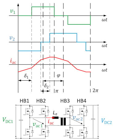
Figure 1. Current and voltage waveform for DAB with TPS and equivalent circuit diagram. Image used courtesy of Bodo’s Power Systems [PDF]
Hardware Setup of the DAB
To characterize the DAB at high power, the test setup in Figure 3 has been built. The core of the power electronics is the 1200 V / 1200 A FMF1200DX1-24A SiC MOSFET half-bridge module. It has integrated short-circuit detection and protection.
As a core material for medium-frequency transformers, nano-crystalline material is often used since it provides high saturation flux density and low losses. However, the transformer in the presented DC/DC converter has a core made of ferrite, which offers a cost-effective solution even compared with a low-frequency transformer. That ferrite core material can be used in such 500 kW converter is enabled by the low switching losses of the SiC power modules and the resulting high switching frequencies. Furthermore, the transformer uses a strip winding for low leakage inductance and forced air cooling. The medium-frequency transformer and its dimensions are shown in Figure 2. The resulting leakage inductance and magnetizing inductance, as well as the DAB parameters, are shown in Table 1. The leakage inductance is a crucial parameter. It limits the rate of current rise in the case of VDC1 ≠ VDC2. Furthermore, according to (3), it must be lower than 3.5 µH to avoid power derating at given DC/DC converter parameters.
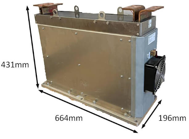
Figure 2. Medium Frequency Transformer. Image used courtesy of Bodo’s Power Systems [PDF]
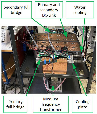
Figure 3. Dual Active Bridge test setup. Image used courtesy of Bodo’s Power Systems [PDF]
Table 1. Dual-Active Bridge and Transformer Parameters
| DAB parameter | ||
| LAC1 | AC1 inductance | 300 nH |
| LAC2 | AC2 inductance | 100 nH |
| VDC1/2 | In- Output voltage range | 500-850 V |
| fsw | Switching frequency | 20 kHz |
| Pout | Nominal output power | 500 kW |
| CDC | DC-Link capacitance | 4.6 mF |
| tdt | Inverter deadtime | 250 ns |
| Transformer parameter | ||
| n | Transfer ratio | 1:1 |
| Lσ,T | Leakage inductance | 200 nH |
| Lh,T | Magnetizing inductance | 250 µH |
| Transformer volume | 56.l l | |
| Transformer weight | Ca. 110 kg | |
| Pmax | Maximum power rating | 640 kW |
To measure the semiconductor losses, a calorimetric measurement system for the DC1 and DC2 side full bridge is implemented. The inlet temperature Tin and outlet temperature Tout as well as the water flow rate Q in each full-bridge cooling plate, is measured separately. With the heat capacity Cp and the density of water ρ, the losses for all full-bridge switches can be calculated according to (5). The overall measurement setup is shown in Figure 6. DC/DC converter input and output are connected and supplied by one power supply. The power drawn by the power supply corresponds to the losses of the DC/DC converter. Hence, accurate power loss measurement of the DC/DC converter is possible. The calorimetric measurement further breaks down between DC1- and DC2-side power module losses and transformer losses.
\[P_{v,calorimetric}=(T_{out}-T_{in})Q\cdot c_{p}\cdot\rho\] (5)
Experimental Results
The experimental results are obtained on the hardware setup previously described and as depicted in Figure 6. For these measurements, only the transfer ratio of one (VDC1 = VDC2) is investigated. The specifications of the prototype are given in Table 1. Measurements were done up to Pout = 504 kW and up to VDC =800V to evaluate the performance.
In Figure 4, the efficiency of the DAB over the transferred power is illustrated. The maximum efficiency is reached for Pout = 110 kW and VDC = 500 V of η=98.24 %. For operation points with low output power, Zero Voltage Switching (ZVS) is not achieved, and efficiency drops accordingly. The calorimetric measurement allows the further breakdown of different loss components. Hence, Figure 5 shows the losses of the DC2-side power module. The power rating, where ZVS is achieved, is clearly visible as power module losses become minimal.
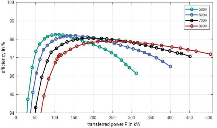
Figure 4. Efficiency of the DAB for different DC-Link voltages VDC and conversion ratio of 1:1. Image used courtesy of Bodo’s Power Systems [PDF]
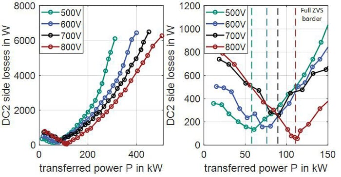
Figure 5. Calorimetric measured losses in DC2 side semiconductor. Image used courtesy of Bodo’s Power Systems [PDF]

Figure 6. Measurement setup for 1:1 operation with calorimetric measurement. Image used courtesy of Bodo’s Power Systems [PDF]
Mitsubishi Electric’s High-Power SiC Power Modules
As shown in the previous chapter, SiC power modules have enabled a 500 kW DC/DC converter to operate at a switching frequency of 20 kHz. For the regarded converter design and its medium-frequency transformer, it was possible to use ferrite core material which has lower core losses compared to conventional silicon steel and is more cost-effective compared to nano-crystalline core material. This game changer was enabled by a 1200 V/1200 A SiC industrial power module from Mitsubishi’s 1st Generation, which has been used in this project.
Table 2. SiC Lineup.
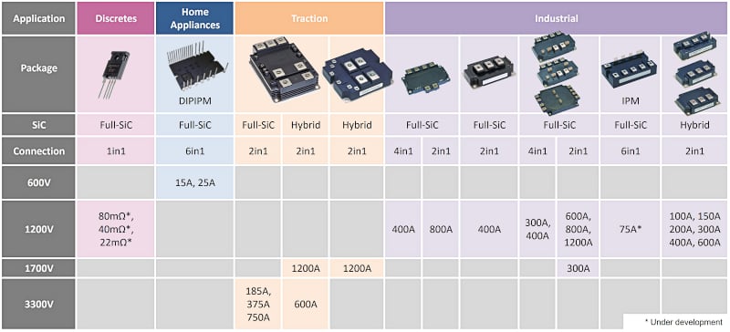
Today, Mitsubishi Electric offers its 2nd Generation industrial SiC Power Modules. The entire SiC line-up is shown in Table 2. The availability of SiC devices for different voltage and current ratings allows competitive DC/DC converter designs for a wide range of applications.
References
[1] Allende, F. R., et. al., Surveying Solid-State Transfomer Structures and
Controls, IEEE Industrial Electronics Magazine, pp. 56-70, March 2020.
[2] Rongwu Zhu, et. al., Operation and Control of the Smart Transfomer in
Meshed and Hybrid Grids, IEEE Industrial Electronics Magazin, pp. 43-57,
March 2021.
[3] Liserre, M., et al., Multiwinding-Transformer-
for Charging Stations, IEEE Electrification Magazine, pp. 5-9, June 2021.
[4] SMA Whitepaper, How DC Coupling Can Increase the Efficiency of Power
Plants, [Online]. Available: www.sma.de/en/products/dc-
converter.html. [Zugriff am 15 August 2022].
[5] Cho, J., et al., Demonstration of a DC Microgrid with Central Operation
Strategies on an Island, in IEEE Third International Conference on DC
Microgrids (ICDCM), Matsue, Japan, 2019.
[6] M. Ocklenburg, M. Döhmen, X. Wu und M. Helsper, Next generation DCDC
converters for Auxiliary Power Supplies with SiC MOSFETs, in IEEE
International Conference on Electrical Systems for Aircraft, Railway, Ship
Propulsion and Road Vehicles & International Transportation Electrification
Conference (ESARS-ITEC), Nottingham, UK, 2018.
[7] N. Schibli, Symmetrical mulitlevel converters with two quadrant DC-DC
feeding, Dissertation, Ecole polytechnique fédérale de Lausanne, 2000.
[8] R. W. A. A. De Doncker, D. M. Divan und M. H. Kheraluwala, A Three-
Phase Soft-Switched High-Power-Density DC/DC Converter for High-Power
Applications, IEEE Transactions on Industry Applications, vol. 27, no.1, pp.
63-73, 1991 Jan 1991.
[9] F. Sommer, N. Soltau, F. Stamer, N. Menger, S. Idaka und M. Hiller, Mirror
Source-based Overcurrent and Short Circuit Protection Method for High
Power SiC MOSFETs, in PCIM Europe digital days, International Exhibition
and Conference for Power Electronics, Intelligent Motion, Renewable Energy
and Energy Management, 2021.
[10] M. Sverko und S. Krishnamurthy, Calorimetric loss measurement system
for air and water cooled power converters, in the 15th European Conference on
Power Electronics and Applications (EPE), 2013.
[11] F. Sommer, N. Menger, T. Merz, N. Soltau, S. Idaka und M. Hiller, Design
and Characterization of a 500 kW 20 kHz Dual Active Bridge using 1.2 kV
SiC MOSFETs, in International Power Electronics Conference (IPEC-Himeji
2022, ECCE Asia), Japan, 2022.
[12] F. Sommer, N. Menger, T. Merz und M. Hiller, Accurate Time Domain Zero
Voltage Switching Analysis of a Dual Active Bridge with Triple Phase Shift,
in 23rd European Conference on Power Electronics and Applications (EPE
‘21 ECCE Europe), 2021.
[13] N. Soltau, E. Thal und T. Matsuoka, The Next Generation of SiC Power
Modules, Bodo’s Power Systems, pp. 22-26, September 2019.
[14] R. Spenke, N. Soltau und T. Matsuoka, Towards a Greener Future: Highly
Efficient SiC Power Devices for Wide Application Range, Bodo’s Power
Systems, pp. 18-25, December 2020.
This article originally appeared in Bodo’s Power Systems [PDF] magazine and is co-authored by M. Hiller, Karlsruhe Institute of Technology (KIT), Karlsruhe, Germany; Dr. N. Soltau and S. Idaka, Mitsubishi Electric Europe B.V., Ratingen, Germany; and T. Hirai, Mitsubishi Electric Corporation, Fukuoka, Japan.