Facebook
 Google
 GitHub
 Linkedin
2 kV SiC Power Modules Transform 1500 V Systems
The newest voltage class of silicon carbide is enabling a shift in circuit topology for 1500 V-class inverters.
This article is published by EEPower as part of an exclusive digital content partnership with Bodo’s Power Systems.
Silicon carbide with blocking voltages up to 1700 V has become prevalent in industrial power conversion due to step improvements in reliability, cost, and system-level value. By extending the blocking voltage of the latest SiC chip generation up to 2000 V, new possibilities arise. DC link voltages that previously required medium voltage devices or multi-level topologies can now be handled more easily.
The newest voltage class of silicon carbide is enabling a shift in circuit topology for 1500 V-class inverters. With proven chip technology, low switching losses, and standard packages, 2 kV SiC power modules are set to revitalize renewable applications and more.
![]()
Image used courtesy of Adobe Stock
Devices for 1500 V Converters
In an effort to reduce direct current and the associated conductor size, many applications have seen an increase in the DC link voltage. In utility-scale solar farms, a study has shown that a 500 V increase can practically reduce DC losses by 0.4%. This results in substantial cost savings over the life of the farm. Closely related Energy Storage Systems (ESS) have benefited from new battery technologies that support increased voltages. In Europe and North America, the upper limit of this increase is 1500 V, as dictated by EU/IEC/UL standards and directives.
Constructing a reliable 2-level converter capable of supporting this DC link voltage requires devices with blocking voltages above the commonly available 1700 V. Medium voltage class silicon IGBTs (e.g., VCES = 3300 V) have been available for many years. However, modern renewable applications have extremely high-efficiency requirements. Such medium-voltage silicon devices have relatively high switching losses due to the chip thickness necessary to maintain such a blocking voltage. This has led to the prevalence of 3-level converters using silicon IGBTs with blocking voltages of 950 V to 1200 V.
Conversely, the high breakdown electric field strength of silicon carbide allows the MOSFET to be fabricated thinner than the equivalent rated silicon IGBT. This results in the well-known fact that SiC devices have dramatically lower switching losses than their Si counterparts. The switching transitions of SiC MOSFETs are so fast that increasing the blocking voltage from 1200 V to 2000 V results in only a marginal increase in switching losses. This is important as the effective ripple frequency in the output current generated by a 3-level converter can be as high as twice the semiconductor switching frequency. Therefore, a 2-level solution using 2 kV SiC must switch at twice the frequency of the 1200 V Si devices used in the 3-level solution (Figure 1).
![]()
Figure 1. 3-level 1200V Si vs. 2-level 2000V SiC phase leg. Image used courtesy of Bodo’s Power Systems [PDF]
Benefits of 2 kV SiC
By looking at a 1 MW converter, it is easy to see the footprint reduction that is possible with 2 kV SiC power modules. As an example, a 1 MW, 1500 VDC, 690 VAC, 3-phase ANPC inverter can be constructed with nine 1400 A/1200 V IGBT half-bridge modules (e.g., SEMITRANS 20). Liquid cooling and a switching frequency of 2.5 kHz are used to achieve a total heatsink footprint of 2000 cm² (Figure 2).
The same power converter can be constructed with only three 2 kV SiC half-bridge modules switching at 5 kHz. This switching frequency yields the same ripple current frequency at the output as the 3-level solution. Moving from nine modules to three modules gives a significant 66% reduction in footprint. This decrease in size obviously means a lower weight for shipping and reduced material usage. However, this size reduction also comes with an improvement in efficiency — total semiconductor losses are reduced by 40%. For this example, this means semiconductor efficiency is 0.4% better than with a 3-level solution — over 99% in both charging and discharging modes.
![]()
Figure 2. Footprint reduction enabled by 2 kV SiC power modules. Image used courtesy of Bodo’s Power Systems [PDF]
While 3-level converters have generally proven to be reliable in the field, the move back to 2-level gives an improvement in the calculated failure rate (FIT) based on the number of electrical components in the system. This is particularly the case when considering the reduction in gate driver channels from 18 (3-level) to six (2-level). Controls are also simplified as a bus voltage balancing algorithm no longer needs to be employed.
New Applications
In addition to replacing existing 1500 V topologies in standalone ESS, 2 kV power modules open opportunities in high-power EV chargers. Trucks and off-road vehicles are already leading the move into battery voltages above 1000 V. To reduce charge times, power is required that is oftentimes greater than what the grid can supply. In these cases, it makes sense to integrate a 1500 V ESS. The ESS provides a reserve of energy that can be quickly transferred to the vehicle battery using a DC/DC converter. DC/DC topologies can present a challenge when isolation is required due to the high frequency needed for transformers. Coupled with high voltage, this means that current solutions use 3-level SiC topologies on the primary side converter. 2 kV SiC power modules simplify this input back to a 2-level H-bridge (Figure 3). To accommodate flexible EV charger applications (high voltage or high current), the output remains as a well-known dual H-bridge configuration.
![]()
Figure 3. Isolated Dual Active Bridge. Image used courtesy of Bodo’s Power Systems [PDF]
Available Modules
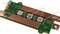
Semikron Danfoss has equipped a range of power modules with the latest generation ROHM Gen. 4 2 kV silicon carbide (Figure 4). These devices feature the robustness and ease of driving of the previously introduced 1200 V Gen. 4 SiC chips but with increased blocking voltage.
![]()
Figure 4. 2kV product portfolio. Image used courtesy of Bodo’s Power Systems [PDF]
The baseplate-less SEMITOP E2 package houses a half-bridge circuit with an RDS(on)_25C of either 6.5 mΩ or 4.3 mΩ. The latter can be used – one module per phase – to construct 3-phase converters beyond 200kW using liquid cooling. Air-cooled designs can even achieve close to 150kW with a single module per phase. The carefully designed pinout, with DC and AC terminals on opposite sides, facilitates easy paralleling. With such hard-paralleled (or interleaved) scheme, 3-phase liquid-cooled converters up to 500 kW can be constructed. The PCB-mount SEMITOP E2 is ideal for modular designs such as those found in UPS systems and modular ESS. The pin-grid reduces loop area for a commutation inductance of only 6 nH. All modules are tested at the end of production with an isolation voltage of 3800 VAC/1s.
For designs above 500 kW and into the multi-MW range, the solution is the new industrial standard SEMITRANS 20. With only four mounting screws and a large internal area for chips, a single SEMITRANS 20 contains a 2 kV MOSFET half-bridge with RDS(on)_25C = 1 mΩ. While large, the SEMITRANS 20 boasts a typical commutation inductance of only 10 nH thanks to its symmetrical internal layout. Semikron Danfoss draws on their years of experience with silver sintering to provide a solder-free connection between chip and substrate. This dramatically helps with power cycling lifetime. Designing silicon carbide devices requires some specialized knowledge. The unique gate voltage requirements and high switching speeds require careful driver design to avoid oscillations, EMI, and outright damage. This is even more critical at high power levels where thousands of amps are switched. Semikron Danfoss provides detailed application notes and reference designs to assist in the design process. But for fastest time-to-market, there is a qualified and tested intelligent power module that integrates driver, SiC MOSFETs, and heatsink. The SKiiP 4 SiC IPM has the same outline and feature set as the proven SKiiP 4 IPM with silicon IGBTs but is equipped with the latest 2kV SiC MOSFETs. This allows the user to very easily reap the benefits this new chipset without a steep learning curve. With half-bridge configurations beyond 1800 A and 900 A sixpacks, this IPM has enough power to create compact highpower converters. Furthermore, the SKiiP 4 SiC IPM promotes supply chain safety by supporting 2 kV chipsets from a variety of suppliers. The digital driver supports the various gate drive voltages required by different SiC chipsets. With sintered chip connections and aluminum-copper bond wires, the SKiiP continues the tradition of being the standard in power cycling capability.
This article originally appeared in Bodo’s Power Systems [PDF] magazine.