Facebook
 Google
 GitHub
 Linkedin
Troubleshooting Single-Phase Induction Motors
Learn how to troubleshoot single-phase induction motors, from diagnosis to fault repair.
Single-phase induction motors are commonly used for rotary motion output in industrial setups. From driving small compressors to large conveyor systems and pumps, these motors offer a versatile option where three-phase power may not be necessary or available. Like any other electromechanical industrial system, single-phase motors need regular maintenance and periodic troubleshooting to ensure efficient operation and prevent failures. Troubleshooting lengthens the motor’s lifespan, reduces power consumption, and helps address faults in the early stages.
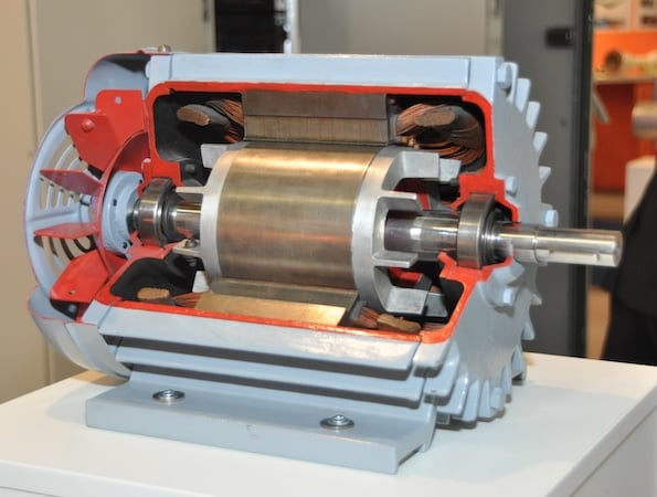
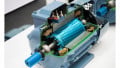
Figure 1. Induction motor cutaway view. Image used courtesy of Wikimedia
Knowing the components comprising a functional single-phase motor is essential for effective fault diagnostics. The main components of a single-phase motor include a stator, which is responsible for generating a magnetic field that induces motion, and the rotor, which forms the rotating element of the motor. Start and run windings, capacitors, bearings, and a centrifugal switch also form the components that make up a single-phase motor. As a maintenance technician or engineer, it's essential to at least have a basic understanding of motor operation and working principles. This saves much time when diagnosing common motor issues and associated symptoms.
Common Issues in Single-Phase Induction Motors
For effective maintenance and troubleshooting, it is essential to understand the common symptoms and issues in single-phase induction motors. A frequent problem is failure to start, resulting from electrical, mechanical, or component failure.
A humming sound is commonly associated with a faulty start capacitor, centrifugal switch, or low power. Without the capacitor, the motor pulsates without rotating, causing the humming. Installing the right capacitor and regularly checking for degradation is essential, as a degraded capacitor may cause reduced starting torque or complete start failure. Choosing a higher capacitance than the one rated for the motor draws excessive current, leading to overheating or failing motor windings.
If the motor temperature rises excessively, the motor could operate beyond the rated capacity, leading to overload due to large amounts of current being drawn in the winding. Continuous exposure to too much heat leads to insulation degradation. To understand the rise in temperature (∆T), consider the surface area of the motor that dissipates heat (A), power loss in the windings (Ploss), and coefficient of heat dissipation (k).
\[P_{loss}=I^{2}R\]
\[\Delta T=\frac{P_{loss}}{A\times k}\]

Figure 2. In single-phase induction motors, the temperature gradually rises as the current increases. Image used courtesy of Bob Odhiambo
Another common issue is unbalanced voltage associated with irregular rotation or excessive vibration. The motor winding’s uneven current distribution can cause magnetic field fluctuation, leading to unnecessary vibration. While troubleshooting, it is essential to check the bearing for wear as it may exhibit similar symptoms or unusual noises such as squealing or grinding. Sporadic motor operations or random on-off operations can be symptoms of a loose connection or thermal overload tripping. If there is an observed inconsistency in the motor's speed, there may be a problem with voltage stability or issues with the power supply.
Knowing where to start during the repair and maintenance of single-phase motors begins by recognizing the symptoms of common issues. This allows for early problem diagnostics, ensuring reliable and efficient motor operation.
Troubleshooting Single-Phase Motors
Systematically approaching troubleshooting, from safety considerations to mechanical inspections, is important.
Prioritize Safety
The first step when troubleshooting single-phase motors is prioritizing safety measures. An engineer must adhere to safety protocols to evade hazards like electric shock, mechanical injuries, and burns.
A fundamental safety precaution is cutting off the single-phase motor's power source. Once the mains supply switch or circuit breaker that powers the motor is located, it should be turned off. Verifying voltage levels can ensure the correct disconnection procedure. To further enhance safety, lockouts/tagouts can eliminate the danger of re-energization. With the power disconnected, it is essential to release any residual energy in the motor’s capacitor and inductive components, as they can store some charges. A final safety consideration is ensuring the appropriate personal protective equipment protects the engineer or technician from hazards like electric shock, arc flash, and legal or financial repercussions from non-compliance.
When discharging the motor's capacitor after power disconnection, follow a safe discharging process by first identifying its location and verifying its rating to use the correct discharge method. A charged capacitor may pose the danger of shock or burn depending on the level of voltage stored in the capacitor. The discharge process can be done using tools like alligator clips or a discharge resistor. With insulated gloves to protect against accidental handling, a technician can place a 10 k discharge resistor, commonly used for low to medium capacitance, across the capacitor's terminals. The resistor should be held in place for some time to allow for complete discharge. Discharge time can be evaluated by considering the resistor value and the capacitance. For instance, an 80 μF capacitor discharged with a 10 kΩ resistor can have its time constant (τ ) evaluated as:
\[\tau = R\times C\]
\[\tau=10,000\times80\times10^{-6}=0.8\,sec\,seconds\]
Therefore, to ensure the capacitor safely discharges, it is advisable to wait for at least 5 times the time constant. In the above case, the wait time is evaluated by multiplying the time constant (0.8 seconds) by 5, which equals 4 seconds. If the motor has multiple capacitors, the discharge process can be carried out for each and confirmed by measuring the voltage across their terminals using a voltmeter if it has dropped in safe handling levels. If acquiring a resistor for the discharge process is difficult, you can connect a lightbulb across the capacitor’s terminals to use the stored energy.
Visual Inspections
Examine the motor and its surroundings for signs of damage, cracks, or dents on its housing, which may otherwise affect its operation by causing vibrations or misalignments. When it comes to wiring, checking for exposed or frayed wires can help identify short circuit issues, paying close attention to sections in the motor where the wire bends or is pressed against sharp bends. To eliminate the potential of poor electrical contact, check the wire and terminal connections for looseness. The terminals can also have damaged screws or cable lags or show signs of oxidation which may affect the motor’s performance by increasing resistance or preventing secure cable connections. Inspect the motor’s start and run capacitor for dielectric leaks or bulges, which are common signs of a faulty capacitor.
Check the environment in which the motor operates and ensure proper ventilation, free from dust and corrosion. These factors greatly contribute to the efficiency and longevity of the induction motor by reducing the cooling efficiency leading to issues that come with overheating.
Electrical and Mechanical Testing
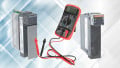
Once the visual inspection is done, electrical testing will be conducted to find issues in the windings or capacitors. To test the motor’s capacitors, set the multimeter to measure the capacitance after discharging the capacitor and compare the readings with the rating. It is essential to ensure that the tolerance of the actual readings against the rating is ±10% for optimal performance. Once done, test the motor's start and run windings winding resistance comparing it with manufacturer specifications. Also, check for continuity to ensure there are no potential short-circuits or broken contacts.
When it comes to mechanical testing, check for wear of bearings and shaft play and consider replacement if faulty. Verify the motor works within its specified mechanical load by comparing its rated capacity with its current load. Finally, check for wear or misalignments of belts and couplings as these may wear off the motor's bearings with its current load. It is also important to inspect the contact and the mechanical operation of the centrifugal switch for damage and replace it if the severity of the damage is high.
Single-Phase Motor Functionality
To maintain the functionality of a single-phase induction motor, engineers must perform regular maintenance and systematically identify issues when motors fail. Timely repairs can extend the motor’s lifespan and reduce downtime expenses.