Facebook
 Google
 GitHub
 Linkedin
Exploring Three-Phase Motors: Types and Operating Principles
This article examines the operational principles and applications of three important types of three-phase motors: squirrel-cage induction, wound-rotor induction, and synchronous.
Three-phase motors—the most widely used in the industry—play a crucial role in various industries. Therefore, it is important to recognize and understand their operating principles.
Squirrel-cage induction motors are known for their simple design, which creates a rotating magnetic field using stator windings. Synchronous speed, which determines motor revolutions, depends on power frequency and stator poles. Wound-rotor induction motors allow variable speed via a three-phase rheostat, but wound-rotor motors have become less popular due to maintenance issues. Synchronous motors, featuring a DC power-supplied rotor, maintain constant speed under different loads, provided they follow correct starting procedures.
This article will examine squirrel-cage induction motors, wound-rotor induction motors, and synchronous motors in more detail.

Image used courtesy of Adobe Stock
Squirrel-Cage Induction Motors
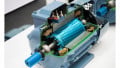
The most widely used motor in industry is the three-phase squirrel-cage induction motor. The squirrel-cage motor in Figure 1 has two parts: the rotor and the three-phase stator. The term armature indicates a rotating component consisting of windings and a commutator, while the term rotor indicates the rotating component of a motor that does not contain windings. Notice the identification of the motor leads labeled T1, T2, and T3. The simple design is one of the squirrel-cage motor’s most attractive features.

Figure 1. The squirrel-cage induction motor. Image used courtesy of Amna Ahmad
The squirrel-cage motor's rotor has no windings. Instead, it consists of metal bars connected at each end-to-end ring. Between the metal bars are sheets of laminated metal. During the motor’s operation, voltage is induced into the metal bars, producing current flow and a magnetic field. In fact, the squirrel-cage motor is named for this rotor, which resembles the exercise wheel commonly found in mouse and hamster cages.
Figure 2 illustrates the three-phase AC power applied to the stator windings. The three-phase power produces a peak voltage every 120°.

Figure 2. The three-phase waveform. Image used courtesy of Amna Ahmad
Now, notice the three separate phase windings in the stator in Figure 3. The phase windings are arranged sequentially around the stator housing. As the applied three-phase power peaks in the positive direction in phase T1, phase windings T2 and T3 will have opposite polarities, and their values will be between 0 and their maximum negative values. As phase T2 peaks in its positive direction, T1 and T3 will have opposite polarities, and their values will be between 0 and their maximum negative values. This pattern continues through the entire 360° rotation of the applied AC sine wave.
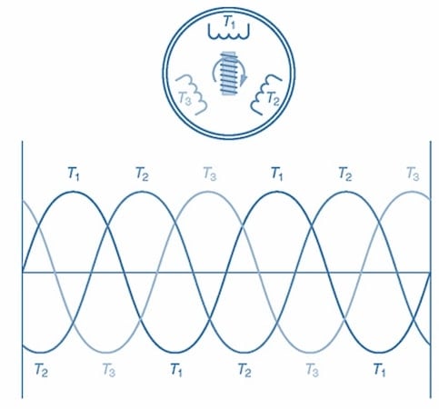
Figure 3. The phase rotation produces a rotating magnetic field in the stator. Image used courtesy of Amna Ahmad
A rotating magnetic field appears around the stator. The speed at which the rotating magnetic speed revolves is the synchronous speed. Synchronous speed is affected by the number of stator poles and the frequency of the applied AC. This relationship is illustrated by the following formula:
\[S=\frac{120\times f}{P}\]
S = Synchronous speed in rpm
F = Frequency of the applied AC in hertz (Hz)
P = number of stator poles
For example, what is the synchronous speed of a four-pole squirrel-cage motor operating from 60-Hz AC power?
What values are known?
F = 60 Hz
P = 4
What value is not known?
S = ?
What formula can be used?
\[S=\frac{120\times f}{P}=\frac{120\times60}{4}=1800\,rpm\]
Therefore, the synchronous speed of this squirrel cage motor is 1800 revolutions per minute.
The rotating magnetic field of the stator induces a voltage into the rotor bars, causing a current flow. The current flow in the rotor bars produces another magnetic field that is attracted to the revolving magnetic field in the stator, causing the rotor to turn and produce torque. However, the rotor will not rotate at the same speed as the rotating field of the stator. Friction in the bearings and wind resistance (windage) will cause the rotor to rotate at a slightly slower speed. This is known as rotor slip. Rotor slip is the difference in speed between the synchronous and rotor speeds.
Until recently, the squirrel-cage motor was considered a fixed-speed motor. As can be seen from the above formula for synchronous speed, the only way to vary the speed of the motor would be to change the frequency of the applied AC voltage or change the number of poles in the motor. Power companies in the United States accurately maintain the power line frequency at 60 Hz. Therefore, changing the frequency of the applied AC power was not an option. It is also not possible to change the number of poles in the motor. The motor would have to be totally rebuilt. Today, however, with electronic variable-speed drives, the frequency of the applied AC power can be varied, and consequently, so can the speed of the squirrel-cage motor. Using solid-state components, electronic variable-speed drives accomplish this by converting the applied AC power to DC, chopping the DC into pulses whose frequency can be varied, and converting those pulses into an artificial AC, which is then applied to the motor. Now, the frequency of the applied AC power can be varied, allowing for variable-speed operation of the motor.
To reverse the direction of rotation of a squirrel-cage motor, simply interchange the connections of any two of the three stator leads. As a rule, T1 and T3 are interchanged. This will cause the rotating magnetic field in the stator to revolve in the opposite direction. The rotor will turn in the new direction of the rotating magnetic field, which will be opposite of the original.
Squirrel-Cage Induction Motor Applications
Squirrel-cage induction motors are extensively used across many industries due to their rugged construction and reliability. One significant application is in industrial machinery, where they power pumps, compressors, and conveyors, providing the necessary torque and speed for efficient operation. Moreover, these motors are commonly integrated into HVAC systems for large commercial buildings and industrial facilities, ensuring proper ventilation and climate control.
In addition, squirrel-cage induction motors can be repurposed as generators by connecting them to a grid supply. In this setup, when the motor shaft is turned manually or by an external force, it induces an electromotive force (EMF) across its windings due to the phenomenon of electromagnetic induction. This EMF creates an AC output that can be fed into the grid supply, effectively converting mechanical energy into electrical power. This application is particularly useful for backup power, in remote locations with unreliable grid connections, or in emergency situations where continuous power supply is crucial.
Wound-Rotor Induction Motors
A variation of the squirrel-cage motor is the wound-rotor induction motor. This motor was designed to meet the need for a variable-speed, three-phase motor. However, as electronic variable-frequency drive use increases, it is becoming less common.
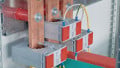
The wound-rotor induction motor consists of a rotor containing windings, slip rings, brushes, and a three-phase stator. Figure 4 shows the parts of a wound-rotor induction motor. Notice the identification of the motor leads labeled T1, T2, and T3 for the stator connections and M1, M2, and M3 for the wound-rotor connections. Figure 4 also shows a three-phase rheostat connected to M1, M2, and M3 in the rotor circuit.

Figure 4. Parts of a wound-rotor induction motor. Only one winding is shown on the rotor shaft for clarity. Image used courtesy of Amna Ahmad
Three-phase power is applied to the stator windings. A rotating magnetic field is created, inducing a voltage into the three-phase rotor windings. This induced voltage produces a current, which creates a magnetic field in the rotor windings. The magnetic field of the rotor interacts with the rotating magnetic field of the stator, causing the rotor to turn. By varying the three-phase rheostat, the strength of the rotor’s magnetic field can be varied. If the magnetic field is lessened, the rotor speed decreases. When the magnetic field is strengthened, the rotor speed increases.
This control over the rotor magnetic field can be used to vary the speed of the wound-rotor induction motor when driving a constant load. In addition, the rotor magnetic field can be varied by an automated process in response to varying load conditions. In this manner, the speed of the wound-rotor induction motor can be held fairly constant.
To reverse the direction of rotation of a wound-rotor induction motor, you simply interchange the connections of any two of the three stator leads. As a rule, T1 and T3 are interchanged. This causes the rotating magnetic field in the stator to revolve in the opposite direction. The rotor then turns in the new direction of the rotating magnetic field, which is opposite from the original.
The wound-rotor induction motor has disadvantages. It is more expensive than a similar-size squirrel-cage motor, requires more maintenance because of brush and slip ring wear, and although it provides variable speed, this benefit has become less attractive because of the use of drives.
Wound-Rotor Induction Motor Applications
Wound-rotor induction motors offer versatility and controllability, making them well-suited for demanding applications. One notable use is cranes and hoists found in manufacturing and construction industries, where precise speed and torque control are essential for safe and efficient lifting operations. Additionally, these motors are commonly employed in mining equipment for heavy-duty tasks, such as driving conveyor belts and powering drilling machinery. Furthermore, they are integral to large-scale pumps and fans requiring variable speed control, ensuring optimal performance and energy efficiency in industrial processes.
Synchronous Motors
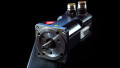
Synchronous motors (shown in Figure 5) have a three-phase stator, a wound rotor, slip rings, and brushes. However, the rotor has a single winding compared to the three windings of the wound-rotor induction motor. The rotor also contains shorting bars similar to the rotor of the squirrel-cage motor. The synchronous motor leads are labeled T1, T2, and T3 for the stator connections and R1 and R2 for the rotor connections. A DC source supplies power to the rotor.
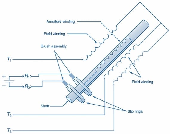
Figure 5. Parts of a synchronous motor. Note the DC applied to the rotor winding. Image used courtesy of Amna Ahmad
Synchronous motors are started by applying three-phase power to the stator. However, power is not applied to the rotor at this time. When the three-phase power is applied to the stator, a rotating magnetic field is created. The rotating magnetic field induces a voltage into the shorting bars of the rotor. This induced voltage produces a current, which creates a magnetic field in the rotor. The rotor is then attracted to the rotating magnetic field of the stator, causing the rotor to turn.
When the rotor is up to speed, the DC source is energized, allowing DC to be applied to the rotor windings. This results in the rotor acting as an electromagnet. The rotor now becomes locked in step with the rotating magnetic field of the stator. This results in the synchronous motor’s ability to operate at constant speed from no-load to full-load conditions. An important rule to remember is that a synchronous motor must never be started with the DC applied to the rotor windings. Should a synchronous motor be started in this fashion, the rotor will fail to turn, damaging the rotor and the DC power supply.
To reverse the rotation of a synchronous motor, simply interchange the connections of any two of the three stator leads. As a rule, T1 and T3 are interchanged, causing the rotating magnetic field in the stator to revolve in the opposite direction. The rotor then turns in the new direction of the rotating magnetic field, which is opposite from the original.
Synchronous Motor Applications
Synchronous motors play critical roles in applications requiring precise speed control and synchronization with power systems. Among their notable applications is power plants, where they are used as synchronous generators to produce electricity with high efficiency and stability. In the marine industry, these motors power propulsion systems in ships and vessels, delivering efficient and responsive performance for navigation. Additionally, synchronous motors are utilized in high-performance industrial machinery like compressors and centrifugal pumps, where accurate speed regulation is crucial for optimal operation and energy savings.
Three-Phase Motor Takeaways
Understanding how three-phase motors operate is essential because they are the backbone of many industrial and power applications, driving a wide range of machinery and processes. The ability to comprehend concepts like synchronous speed, rotor slip, and variable-speed operation allows engineers to troubleshoot and effectively manage these motors. Moreover, recognizing the differences between these motor types, their advantages, and limitations provides a foundation for informed decision-making in motor selection for diverse applications.