Facebook
 Google
 GitHub
 Linkedin
Three-Phase Induction Motor Operation Explained
This article describes the operating principles and equivalent circuits of a three-phase induction motor.
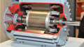
An induction motor is an AC machine in which alternating current is directly supplied to the stator armature windings and indirectly to the rotor windings by induction or transformer action from the stator. Hence, it is also referred to as a rotating transformer. Its stator windings are similar to those of synchronous machines. However, the induction motor's rotor can be one of two types:
- Wound rotors have three windings, similar to stator armature windings. The rotor winding terminals are connected to insulated slip rings installed on the rotor shaft. The carbon brushes mounted on these rings give the machine operator access to the rotor terminals. During steady-state operation, these terminals are shorted.
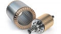
- In squirrel-cage rotors, conducting bars are fixed in slots in the rotor magnetic core, and the bars are short-circuited at both ends by conducting end rings. Since the rotor bars and short-circuit rings are shaped like a squirrel cage, the rotor is termed a squirrel-cage rotor.
Most induction motors have squirrel-cage rotors, however, the two types of rotors are similar from a modeling point of view.
The three balanced alternating voltages applied to the stator cause balanced stator currents to flow. These stator currents generate a rotating mmf that can be characterized as a rotating magnetic field. According to Faraday's law of electromagnetic induction, this rotating magnetic field induces voltages in the rotor windings. These induced voltages cause balanced currents to flow through the short-circuited rotor. These rotor currents generate a rotor mmf, which can also be characterized as a rotating magnetic field. As a result of the interaction between these two rotating magnetic fields, an electromagnetic torque Te is produced, which is used to turn a mechanical load Tm. In a steady state condition, when the motor losses are ignored, Tm and Te are equal.
The motor windings are inductors, and energy is stored in the windings through magnetic fields.
The speed of rotation of the rotor magnetic field, when viewed from a stationary position on the stator, is equal to the speed of rotation of the stator magnetic field, which is the synchronous speed ns. However, the rotor speed nr is different from the synchronous speed. If nr were equal to ns, there would be no variation of flux linkage in the rotor, or there would be no net flux cutting; hence, no voltage would be induced in the rotor. Therefore, rotor speed has to be less than synchronous speed. The difference in speed is represented by the slip s, which is defined as:
\[s=\frac{n_{s}-n_{r}}{n_{s}}\,\,\,(1)\]
Where
nr = rotor speed (rpm)
ns = \(\frac{120f}{p}\) = synchronous speed (rpm)
p = number of poles
The difference between the speed of the rotor magnetic field and the speed of the stator expressed in revolutions per minute is called slip rpm and is equal to (ns – nr). Therefore, the frequency of the rotor currents is determined by:
\[f_{r}={\big(}n_{s}-n_{r}{\big)}\frac{p}{120}=s{\Big(}\frac{pm_{s}}{120}{\Big)}\,\,\,(2)\]
Since \(\frac{pm_{s}}{120}\) is equal to the frequency of the stator currents, Equation 2 can also be written as:
fr = sf (3)
For steady-state operation, the slip has a normal range of values between 1% and 5%.
Development of Equivalent Circuit in a Three-Phase Induction Motor
An equivalent circuit is invaluable in the performance analysis of the three-phase induction motor. Therefore, the equivalent circuit, as well as approximate equivalent circuits, are developed in this section.
The general form of the equivalent circuit for a three-phase induction motor can be derived from the equivalent circuit of a three-phase transformer. The induction motor can be considered a three-phase transformer whose secondary, or the rotor, is short-circuited and revolves at the motor speed. Since the motor usually operates at balanced conditions, only a single-phase equivalent circuit is needed.
When balanced three-phase currents flow in both stator and rotor windings, the resultant synchronously rotating air-gap flux wave induces balanced three-phase voltages in both stator windings and rotor windings. The stator-induced voltage has a frequency equal to the frequency f of the applied voltage, while the rotor-induced voltage has a frequency fr given by Equation 3.
Consider the stator first. The applied voltage per phase across the stator terminals is equal to the sum of the stator-induced voltage per phase, plus the voltage drop across the stator winding resistance, plus the voltage drop across the stator leakage reactance due to the leakage flux, which links only the stator winding. Mathematically, in phasor form, the relationship may be expressed as:
V1 = E1 + R1I1 + jX1I1 = E1 + I1(R1 + jX1) (4)
Where
V1 = stator terminal voltage per phase
E1 = stator-induced voltage per phase
I1 = stator current per phase
R1 = stator winding resistance
X1 = stator winding reactance
The magnetic core can be modeled as a parallel combination of a resistance Rc to account for hysteresis and eddy current losses and a reactance Xm to account for the magnetizing current required to produce the air-gap magnetic flux. The magnetizing current in an induction motor is much larger than that in a transformer because of the presence of the air gap in a motor.
Next, a model of the rotor is developed. Let E2 denote the rotor-induced voltage at a standstill, that is, s= 1.0. At a standstill, the induction motor may be viewed as a transformer with an air gap, and the stator per-phase induced voltage E1 is related to the rotor per-phase induced voltage E2 by the turns ratio (N1/N2) that is:
\[E_{1}={\Big(}\frac{N_{1}}{N_{2}}{\Big)}E_{2}\,\,\,(5)\]
Where
N1 = number of turns in the stator winding
N2 = number of turns in the rotor winding
The voltage induced in the rotor of the induction motor is directly proportional to the relative motion of the rotor and the synchronously rotating air-gap magnetic field. When the induction motor is rotating at a speed n or a slip s, the rotor-induced voltage E2s equals the induced voltage at standstill E2 multiplied by the slip. In the short-circuited rotor circuit, the induced voltage E2s appears as a voltage drop across the rotor resistance and leakage reactance.
The rotor resistance does not depend on the slip. However, the rotor leakage reactance does and is equal to Xr = 2πfrLr = s2πfLr, where Lr is the leakage inductance of the rotor winding due to flux linking the rotor winding only. Thus, the rotor-induced voltage at slips may be expressed mathematically as follows:
E2s = sE2 = IrRr + j(2πfrLr)Ir
=IrRr+js2πfLrIr
= IrRr + jsX2'Ir (6)
Where
E2s = rotor-induced voltage at slip s
E2 = rotor induced voltage at standstill (s = 1.0)
Ir = rotor phase current
Rr = rotor resistance per phase
X2' = 2πfLr = rotor leakage reactance per phase at a standstill
Dividing both sides of Equation 6 by the slip s and referring rotor quantities to the stator side, as in a transformer, yields
\[E_{2}={\Big(}\frac{R_{r}}{s}+jX^{'}_{2}{\Big)}I_{r}\]
\[{\Bigg(}\frac{N_{1}}{N_{2}}{\Bigg)}E_{2}={\Bigg(}\frac{N_{1}}{N_{2}}{\Bigg)}^{2}{\Bigg(}\frac{R_{r}}{s}+jX^{'}_{2}{\Bigg)}{\Bigg(}\frac{N_{2}}{N_{1}}{\Bigg)}I_{r}\]
\[E_{1}={\Bigg(}\frac{R_{2}}{s}+jX_{2}{\Bigg)}I_{2}\,\,\,(7)\]
Where
E1 = (N1/N2) E2 = rotor-induced voltage referred to the stator
I2 = (N2/N1) Ir = rotor current referred to the stator
R2 = (N1/ N2) R1 = rotor resistance referred to the stator
X2 = (N1/ N2)2 X2' = rotor leakage reactance referred to the stator
The stator circuit represented by Equation 4 and the rotor circuit represented by Equation 7 are at the same frequency f of the applied voltage. Therefore, these stator and rotor circuits can be joined together and combined with the model of the magnetic core into the per-phase equivalent circuit of the induction motor, which is shown in Figure 1.
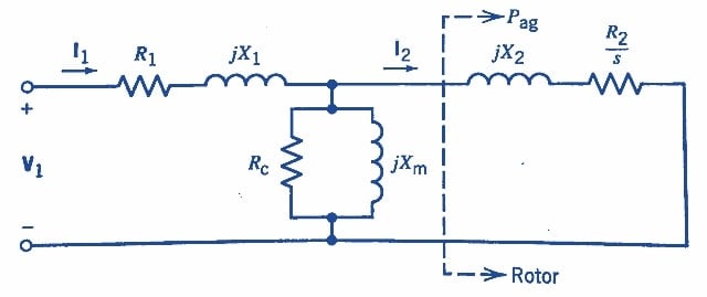
Figure 1. Per-phase equivalent circuit of a three-phase induction motor. Image used courtesy of Amna Ahmad
An approximate equivalent circuit for an induction motor is derived by moving the shunt elements, Rc and Xm, in parallel, representing the core to the motor terminals. This simplification introduces little error but greatly reduces the computational effort. This approximate equivalent circuit is shown in Figure 2. Also shown in the figure is the equivalent rotor resistance R2/s, which has been decomposed into R2 and R2[(1-s)/s]. The first resistance component, R2, represents the rotor copper loss, and the second component represents the power developed by the motor.
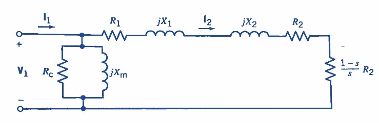
Figure 2. Approximate equivalent circuit of an induction motor. Image used courtesy of Amna Ahmad
Induction Generators
Just like DC and synchronous machines, the induction machine may be used as a generator or motor. Because their performance cannot compare with synchronous machines, induction generators have yet to be very popular. In recent years, however, induction generators have found use in wind power plants. Because of its wide use and popularity, the induction motor is called the workhorse of the power industry, which works on the principle of electromagnetic induction.
Featured image used courtesy of Adobe Stock