Facebook
 Google
 GitHub
 Linkedin
PV Problem Troubleshooting: Arrays, Batteries, Inverters & More
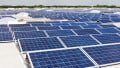
This article examines troubleshooting for photovoltaic system issues related to arrays, electrical loads, batteries, charge controllers, and inverters.
The best way to avoid system failures is to install a high-quality, properly designed PV system. A regular maintenance program helps eliminate system failures. The most common system failures are usually the easiest to fix. Check the system first for basic problems to save a lot of time. The most common system failures are blown fuses, tripped circuit breakers, and bad connections.
Start With the Inverter
A good place to start is to check the output of the system at the inverter. Before going to the array location, check and record the inverter’s input and output voltage and current with a True RMS multimeter. If there is voltage on the input side of the inverter but no output side voltage, there is most likely an inverter problem. If the input side voltage and current from the PV system array are operating at a reduced level, the problem is most likely with an array string or with a specific module. This means you’ll need to go to the array location next.

Image used courtesy of Adobe Stock
In a grid-tied PV system, the AC output from the inverter fluctuates with the amount of sun. The inverter provides for the correct output voltage and frequency to the utility.
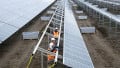
When you get to the array location, check the entire system for any obvious damage. When inspecting the array, look for broken wires and loose or dirty connections. Repair broken wiring, tighten loose connections, and clean dirty connections as needed. Determine the wiring paths from the combiner box (if one is used) to the module strings. Once you find the module or array string that is not producing power, check all wiring, diodes, fuses, or circuit breakers, and replace any defective items. If necessary, replace the defective module or modules. Remember that a lightning strike or power surge may have occurred, and you may have to replace or reset a surge protection device.
Combiner boxes are often the best place to troubleshoot the system because the individual wires from the array strings are terminated there. In the combiner box, each string has a fuse or circuit breaker. Check for blown fuses, tripped circuit breakers, and loose connections.
Look for any dirt on the modules or modules that are in the shade because either situation can cause reduced module output. Pollen can also be a problem in some areas.
If no problem is found at the array or inverter, check the building’s electrical loads to make sure the proper voltage is present at the loads’ branch circuits originating in the AC load entry. If there are DC loads, check the DC load entry. Then, check the overcurrent protection devices in the DC or AC load entries. If blown fuses or tripped breakers exist, identify the cause and repair or replace the offending component. If the load still does not operate properly, the wire size may be too small so that there is too much voltage drop in the circuit. The branch circuit wire running to the load also may be too long. If this is the case, increase the branch circuit wire size or decrease the length of the circuit. If possible, reduce the load on the circuit.
PV System Troubleshooting Guide
Many PV system component manufacturers include troubleshooting guides in the product’s owner’s manual. The following guide will help you identify the problem and a possible cause, as well as provide a fix. The guide is broken down into the main parts of a PV system, including the array, electrical load, batteries, charge controller, and inverter.
|
PV System Troubleshooting Guide |
||
|
Array |
||
|
Problem |
Possible Cause |
Fix |
|
The array has a reduced output or no output at all. |
Wire connections are poor or loose. |
Tighten all wire connections according to the manufacturer’s specifications. |
|
|
The modules are dirty. |
Clean the modules with a mild soap and water solution. |
|
|
One or more modules are defective. |
Check the Voc of each module in a string to determine whether there are any defective modules. For long strings, divide the string in half and decide which half is faulty. Then, use the same method to zero in on the defective module(s). Replace defective modules as necessary. |
|
|
In the combiner box, fuses are blown or circuit breakers tripped. |
Determine the cause of the blown fuse(s) or tripped circuit breakers. Repair the cause and replace fuses or reset circuit breakers. |
|
|
Bypass diodes are defective. |
Test bypass diodes and replace defective diodes as needed. |
|
|
There is excessive array shading. |
Determine the cause of the shading and take necessary steps to eliminate the causes(s). |
|
Electrical Load |
||
|
Problem |
Possible Cause |
Fix |
|
An electrical load is not working. |
In the load center, a fuse is blown or a circuit breaker is tripped. |
Determine the reason a fuse blew or a circuit breaker tripped. Fix the problem and then reset the circuit breaker or replace the fuse. |
|
|
The inverter has switched off. |
Check the inverter using the manufacturer’s troubleshooting guide to determine what caused the inverter to shut down. |
|
|
There is an open circuit. |
Check the circuit for continuity. Tighten any loose connections. Repair any breaks in the circuit wiring. |
|
|
The load’s thermal overload device has activated. |
Wait for the device to cool down, and then reset it. |
|
|
The surge capacity of the inverter is not high enough. |
Reduce the load. If this isn’t possible, install a larger inverter. |
|
Batteries |
||
|
Problem |
Possible Cause |
Fix |
|
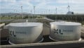
Batteries are undercharged. |
The system array is not producing enough charging current because of an extended length of time with cloud cover. |
Reduce the building’s electrical load or adjust the PV system size for more days of autonomy. |
|
|
The building’s actual electrical load is greater than the calculated load. |
Reduce the building’s electrical load or increase the size of the PV system. |
|
|
The battery fluid level is too low. |
Inspect the fluid levels and fill with distilled water as necessary. |
|
|
The specific gravity of the batteries is low. |
Perform a load test on the batteries and replace any defective batteries. |
|
|
The batteries are old or have been deep cycled regularly, resulting in reduced capacity and the ability to accept a charge. |
Replace the battery bank with new batteries. |
|
|
An excessive voltage drop in the wiring from the array to the battery bank. |
Increase the wire size or reduce the length of the wire run. |
|
|
The batteries are too cold and need a higher voltage to achieve full charge. |
Insulate the battery box and/or use a charge controller with a temperature-compensation feature. |
|
|
If a temperature sensor is used, the sensor wire is damaged. |
Repair or replace the temperature sensor wire. |
|
|
The controller may not allow full charge current even with the charging light on. |
Check the high-voltage disconnect (HVD) setting on the charge controller and reset it to the proper value. If necessary, replace the controller. |
|
Batteries are overcharging and/or have too much fluid loss. |
The charge controller is not receiving the true battery voltage. |
Check the high-voltage disconnect (HVD) setting and reset to the proper value. Also, check the temperature-compensation sensor connections and repair if necessary. |
|
|
The temperature-compensation sensor or the sensor wiring may be damaged. |
Check the temperature-compensation sensor and wiring. Repair or replace as necessary. |
|
|
The battery temperature is too high. |
Insulate the battery box and/or use a charge controller with a temperature-compensation feature. |
|
|
The controller constantly applies a full charge to the batteries, resulting in a higher-than-normal voltage. |
Check the battery voltage and determine when the controller switches from full charge to maintaining the charge. Adjust the controller as needed according to the manufacturer’s instructions. |
|
Charge Controller |
||
|
Problem |
Possible Cause |
Fix |
|
The charge controller isn’t working properly. |
The array may have been disconnected and upset the controller’s timer circuitry sequencing. |
Disconnect the array again and wait 10–20 seconds before reconnecting the array to reset the controller’s timer cycle. |
|
|
Inverters and some load types can generate electrical noise that affects controller operation. |
Connect the inverter directly to the batteries or add filtering to the loads. |
|
|
The batteries in the bank have deteriorated and have voltages that can vary greatly. |
Replace the batteries. |
|
The controller display indicates a low light condition under all conditions. |
The PV wires from the array may be connected in reverse polarity, or there could be a short circuit in the PV input, resulting in zero volts of input voltage. |
Verify the PV array wiring polarity relative to battery negative. Check for a short circuit in the PV input circuit and repair it. |
|
Controller input and output voltages read about the same. |
The maximum power point of the array is lower than the nominal battery voltage. The controller is still charging but cannot charge at Vmpp. |
Check and reconfigure the array as needed. |
|
Uneven output current between multiple controllers. |
PV array sections are supplying different amounts of current to each charge controller. |
Check the array section outputs and adjust for any differences. Consider that this could be a normal operating condition if the array sections are located in different locations and/or point in different directions. |
|
|
Charging set points are not all set the same. |
Set controllers to the same settings. |
|
|
Excessive voltage drop in the wiring is leading controllers to measure the battery voltage differently and regulate accordingly. |
Check wiring. Installing larger wire or shortening the wire runs may be required. |
|
|
Chargers are in Constant Voltage (absorption) mode and, therefore, limiting their output current to maintain the present battery voltage. In this situation, some units produce more output current than others. |
There is no need for intervention, as this is a normal operating condition. |
|
Battery voltage exceeds Bulk and Float settings during cold weather and fails to reach these settings during hot weather. |
The battery temperature sensor is compensating charging voltages based on battery temperature. |
This is not a problem; it is supposed to happen. |
|
The display indicates a ground fault, and the controller has stopped operating. |
A ground fault has triggered the activation of the ground fault protection (GFP) device, indicating a severe leakage between the PV array and the earth ground. |
Identify and repair the cause of the ground fault and reset the GFP device. This may include replacing a blown fuse or resetting a circuit breaker. |
|
Inverter |
||
|
Problem |
Possible Cause |
Fix |
|
The inverter’s display and indicator lights are blank, and the inverter does not operate even when the sun is shining on the array. |
The DC and/or AC disconnect switch is OFF. |
Turn on the DC and/or AC disconnect switch and follow the inverter start-up procedure as outlined in the owner’s manual. |
|
The display indicates that the inverter is offline and/or there is an AC voltage fault. |
The load center circuit breakers are off. |
Turn on the load center circuit breakers. |
|
|
AC utility grid voltage is not present or is incorrect. |
Check the AC connections at the inverter’s terminals. Make sure the AC voltage is within the range specified in the owner’s manual. |
|
The display indicates that the inverter is offline even when the sun is shining on the array. |
DC breakers are switched off, or external DC fuses are blown. |
Turn on DC breakers and inspect DC fuses. Replace blown fuses as necessary. |
|
|
DC array voltage is not present. |
Examine the DC connections at the positive and negative terminals of the inverter. Check the PV array for any incorrect wiring. |
|
The display indicates that the inverter is offline and that there is a DC voltage fault even when the sun is shining on the array. |
DC voltage is present, but it is not the correct value. |
Examine the DC connections at the positive and negative terminals of the inverter. Check the PV array for any incorrect wiring. Ensure that a voltage within the operating voltage range is present at the input terminals of the inverter. |
|
The inverter’s display indicates a ground fault. |
A ground fault condition has been detected in the PV array. |
The PV array should be checked and any faults to ground repaired. |
Sustainable, Efficient Energy Production
A well-maintained and properly functioning PV system is crucial for ensuring sustainable and efficient energy production. The troubleshooting techniques outlined in the article play an essential role in addressing common issues that may arise in different components of the system, ranging from the array to the inverter. Regular maintenance and timely problem resolution are vital for maximizing the system's lifespan and performance. Moreover, the comprehensive troubleshooting guide provides a valuable resource for users, emphasizing the importance of proactive measures to detect and rectify issues promptly, contributing to the overall reliability of photovoltaic systems in various applications.