Facebook
 Google
 GitHub
 Linkedin
Transmission Line Losses and Efficiency Optimization—Part 5: FACTS
Learn about the role of Flexible AC Transmission Systems (FACTS) in enhancing power system efficiency, stability, and controllability. We’ll look at operating principles, control strategies, and more.
Flexible AC Transmission Systems (FACTS) enhance grid performance by using power electronic devices to dynamically control voltage and reactive power. STATCOM operates through voltage-source converters that inject or absorb reactive power rapidly and effectively, even during deep voltage sags, making it well-suited for systems with high renewable penetration.
In contrast, SVC uses thyristor-controlled reactors and switched capacitors to provide reactive support, offering reliable performance in stable, predictable load environments but with slower response and reduced effectiveness under low-voltage conditions. Both devices are critical for voltage regulation, loss reduction, and improving the utilization of existing transmission infrastructure.
Power System Efficiency and Stability
The rapid growth in electricity demand, increased interconnection of transmission systems, and integration of variable renewable energy sources have placed unprecedented pressure on power system operators to maintain both efficiency and stability. Efficiency in this context refers not merely to minimizing transmission losses (I²R losses), but also to optimizing power flow, reducing congestion, and maximizing utilization of existing infrastructure. Simultaneously, the stability of the power grid—encompassing voltage, frequency, and rotor angle stability—has become more difficult to preserve due to the dynamic and nonlinear behavior of modern networks.
Historically, power systems were designed with large synchronous generators and relatively predictable load centers. However, the decentralization of generation (for example, solar PV, wind farms) and increase in load volatility have introduced challenges that traditional grid control methods—based on fixed impedance transmission corridors and electromechanical regulation—are ill-suited to handle. As a result, real-time control capabilities that can dynamically adapt to changing system conditions are no longer optional—they are essential.
Complexity in Modern Transmission Networks
The topology of modern transmission networks is increasingly meshed and interconnected across regions, driven by both economic dispatch considerations and resilience goals. However, this interconnectivity creates power flow coupling and sensitivity issues, where changes in one part of the system can produce cascading effects elsewhere. This complexity is compounded by:
Nonlinear load characteristics and reduced system inertia due to inverter-based generation
- Dynamic load variations influenced by industrial cycling and prosumer behavior
- Voltage instability phenomena in long EHV transmission lines and load centers far from generation sources
Conventional grid devices—such as mechanically switched capacitors, reactors, and transformer tap changers—lack the speed, precision, and controllability required for real-time operation under these conditions. Furthermore, building new transmission lines is capital-intensive and frequently constrained by environmental, regulatory, or land-use challenges. This has shifted focus toward increasing the controllability and efficiency of existing transmission assets—a core capability of FACTS.
Role of Flexible AC Transmission Systems (FACTS)
Flexible AC Transmission Systems (FACTS), as defined by IEEE, are power electronic-based devices that provide dynamic control of voltage, impedance, and phase angle in AC transmission systems. They enable fast and continuous control over key parameters that directly affect power transfer capability, voltage regulation, and system damping.
Mathematically, the real power P transferred between two buses in a lossless transmission line is given by:
$$P = \frac{V_1 V_2}{X} \sin (\delta)$$
where:
V1 and V2 are bus voltages
X is the line reactance
δ is the phase angle difference.
FACTS devices can directly influence each of these variables:
- STATCOM and SVC adjust the local voltage magnitude V via reactive power injection or absorption.
- TCSC modifies the effective line reactance X, thereby controlling the power flow.
- UPFC (Unified Power Flow Controller) can simultaneously regulate voltage, impedance, and phase angle.
These devices allow operators to modulate power flows dynamically across transmission corridors, provide voltage support during disturbances, and mitigate subsynchronous resonance or oscillations. In doing so, they reduce thermal overloads, minimize losses, and improve overall system reliability without the need for large-scale infrastructure expansion.
Overview of Flexible AC Transmission Systems (FACTS)
Flexible AC Transmission Systems (FACTS) are defined by the IEEE as “a power electronic-based system and other static equipment that provide control of one or more AC transmission system parameters to enhance controllability and increase power transfer capability.” FACTS devices operate by injecting controllable voltage or current components into the system, thereby adjusting key transmission variables such as voltage magnitude, line impedance, and phase angle.
As the table below shows, FACTS devices are categorized based on their mode of connection to the power system:
| Category | Description | Examples |
| Shunt Controllers | Connected in parallel with the transmission line | STATCOM, SVC |
| Series Controllers | Connected in series with the transmission line | TCSC, SSSC |
| Combined Controllers | Incorporate both series and shunt elements | UPFC, IPFC |
This classification reflects the physical topology and the function provided by each class—shunt controllers primarily manage voltage and reactive power, series controllers control line current and power flow, and combined controllers simultaneously modulate multiple parameters.
System Benefits of FACTS Implementation
FACTS devices offer a range of benefits critical to modern transmission planning and operation. These include:
- Dynamic Voltage Control: Shunt devices (for example, STATCOM, SVC) provide rapid reactive power compensation, stabilizing voltage profiles under dynamic loading or fault conditions.
- Power Flow Control: Series devices (for example, TCSC, SSSC) alter line impedance and phase angle, redistributing power flows in meshed networks.
- Increased Transmission Capacity: By improving voltage profiles and managing thermal limits, FACTS devices allow existing lines to carry more power safely.
- Enhanced Stability: FACTS can dampen power oscillations, mitigate subsynchronous resonance (SSR), and improve both transient and small-signal stability.
- Reduced Transmission Losses: By improving power factor and load balancing across multiple corridors, FACTS devices help reduce I²R losses.
These benefits translate to improved asset utilization, delayed need for network expansion, and increased resilience against disturbances. In highly stressed systems, the ability to control power flow and maintain voltage within tight tolerances is particularly critical.
STATCOM and SVC: Reactive Power Compensation
Reactive power control is essential for maintaining voltage stability in transmission systems. In an interconnected AC grid, nodal voltage magnitude is highly sensitive to the reactive power balance at that node. This relationship can be rigorously understood through the power flow Jacobian, particularly the submatrix involving partial derivatives of reactive power with respect to voltage magnitude. At a high level, this sensitivity implies that even small disturbances in load or generation can trigger disproportionate voltage swings, especially in weak systems with low short-circuit ratios or extended high-impedance lines.
Without sufficient reactive compensation, transmission networks are vulnerable to voltage instability phenomena, such as progressive voltage drops, delayed voltage recovery following faults, and in severe cases, voltage collapse. Dynamic reactive power compensators such as STATCOM and SVC provide precisely the modulation necessary to stabilize voltage under real-time operating conditions, by injecting or absorbing reactive power in response to local voltage deviations.
STATCOM: Operation, Control, and Capabilities
The Static Synchronous Compensator (STATCOM) is a voltage-source converter (VSC)-based device that regulates reactive power by synthesizing a controllable AC voltage behind a coupling reactance. When the converter output voltage exceeds the grid voltage, the device injects capacitive reactive power; when it is below the grid voltage, it absorbs inductive reactive power. This bidirectional capability is enabled through pulse-width modulation or space vector modulation schemes applied to the IGBT- or IGCT-based converter bridge.
$$|V_C| > |V_S| \text{ for capacitive behavior}$$
$$|V_C| < |V_S| \text{ for inductive behavior}$$
The dynamic behavior of a STATCOM is best understood in the rotating dq-reference frame, where the converter’s d- and q-axis current dynamics are governed by coupled differential equations. The control objective is to regulate the q-axis current component, which directly corresponds to reactive power.
This is achieved through cascaded control loops: a fast inner current controller, typically implemented in the synchronous reference frame, and an outer voltage regulation loop that adjusts the reactive power reference to maintain the bus voltage at a target setpoint. A phase-locked loop (PLL) ensures synchronization with the grid’s voltage vector, allowing precise decoupling of active and reactive power channels.
One of the most important features of STATCOM is its ability to provide full reactive current injection even at low voltages, where traditional SVCs tend to lose effectiveness. This characteristic is critical during transient conditions such as faults, where the voltage at the point of common coupling may drop to 0.6–0.7 pu or lower. STATCOM’s control can sustain reactive current injection nearly proportional to the rated capacity, preserving system voltage stability and satisfying stringent low-voltage ride-through (LVRT) requirements defined in grid codes such as IEEE 2800 or ENTSO-E’s network codes.
Moreover, due to its solid-state switching and high-frequency modulation, the STATCOM responds within 2–10 milliseconds—far faster than any mechanically switched or thyristor-controlled alternative.
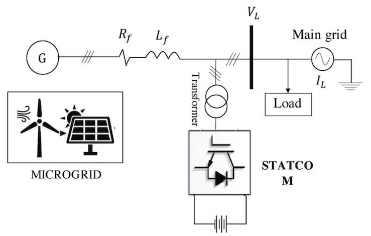
Figure 1. STATCOM for Reactive Power Compensation. Image used courtesy of IntechOpen.
SVC: Architecture, Control, and Limitations
In contrast to the STATCOM, the Static Var Compensator (SVC) is built from thyristor-controlled reactors (TCRs) and thyristor-switched capacitors (TSCs). The TCR allows continuously variable inductive compensation by adjusting the firing angle of the thyristors, effectively modulating the conduction window of the reactor current. The relationship between the firing angle and reactive power is nonlinear and described by a well-known equation that reflects the harmonic content and the non-sinusoidal conduction of the reactor.
$$Q_{TCR}(\alpha) = \frac{V^2}{\omega L}\left(1 - \frac{2 \alpha}{\pi} - \frac{1}{\pi}\sin(2\alpha)\right)$$
where:
QTCR is the reactive power absorbed by the reactor (in VARs)
V is the RMS line-to-neutral voltage
L is the reactor inductance
ω = 2πƒ is the angular frequency
α is the thyristor firing angle
TSCs, on the other hand, provide stepwise capacitive compensation, with fixed-size capacitor banks that are switched into the circuit as needed. Unlike TCRs, the TSCs are turned on at voltage zero-crossings to avoid transients and cannot be modulated continuously. This means that while the SVC offers relatively fast reactive support on the inductive side (via TCRs), its capacitive compensation is inherently quantized, resulting in limited precision under rapidly varying conditions.
$$Q_{TSC} = \omega C V^2 $$
where:
C is the capacitance of the bank
V is the RMS line-to-neutral voltage
Since the TSC can only be fully switched on or off, there’s no firing angle modulation. The capacitive compensation is therefore quantized in discrete steps, determined by the number and rating of the switched capacitor banks.
In steady-state or slowly varying systems, particularly those with predictable industrial loads or sub-transmission applications, SVCs can provide robust and reliable voltage support. However, during deep voltage depressions, such as those caused by short circuits or fault clearing events, the effectiveness of an SVC diminishes. Since its reactive current output is voltage-dependent, the VAR injection capability deteriorates as voltage drops, making it less effective for dynamic voltage support compared to a STATCOM.
Furthermore, the thyristor-based switching in SVCs introduces significant harmonics into the system, particularly from the TCR branches. As a result, SVC installations often require extensive filtering—both tuned and high-pass—to comply with harmonic distortion limits specified in standards like IEEE 519. Their response time, though faster than mechanically switched capacitors, typically ranges between 20–50 milliseconds, which limits their effectiveness in ultra-fast dynamic scenarios such as those encountered in renewable generation integration or post-fault recovery.
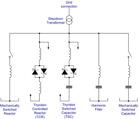
Figure 2. One-line diagram of a typical SVC Configuration. Image used courtesy of Wikipedia.
Performance Comparison in Voltage Regulation Scenarios
Both STATCOM and SVC are deployed to regulate bus voltage by adjusting reactive power output according to real-time system conditions. However, the differences in their dynamic behavior, control flexibility, and voltage dependence produce significantly different performance outcomes in practical grid applications.
In a heavily loaded transmission corridor, for instance, with long EHV lines and limited local generation, sudden changes in load can lead to voltage sags or swells that must be compensated within a few cycles to prevent cascading instability. A STATCOM, with its fast response and full-capacity injection even during voltage sags, can rapidly restore the voltage to acceptable levels.
In contrast, an SVC in the same scenario may fail to deliver the required reactive support if the voltage dips too low, because its thyristor-controlled reactors rely on sufficient voltage for current conduction.
Similarly, in systems dominated by inverter-based generation—such as wind and solar farms—grid codes mandate that reactive support be provided during fault events and recovery periods. STATCOMs are frequently installed at the point of interconnection in such systems, not only to provide fast voltage support but also to contribute to system inertia via synthetic inertia algorithms. Their controllability allows participation in grid-forming or grid-following control modes, making them integral to the stability of high-renewable grids.
Practical Deployment
STATCOMs are increasingly deployed in weak grid regions, particularly at the interface of large renewable power plants, where their high dynamic range and low-voltage performance are essential. In addition to voltage support, they are used for flicker mitigation, dynamic stability enhancement, and damping of low-frequency oscillations. Notable deployments include offshore wind integration projects, where transmission distances and limited fault levels make dynamic compensation crucial.
SVCs remain popular in transmission substations and industrial plants where load patterns are cyclic but predictable, such as arc furnaces or cement mills. Their robustness, proven technology base, and cost advantages make them suitable for installations where ultra-fast dynamics are not critical. Despite their limitations, they continue to offer a reliable solution for systems where harmonic filtering is already part of the infrastructure or where cost is a key consideration.
Key Takeaways
In modern power systems characterized by high renewable integration, dynamic load behavior, and increasing network complexity, devices like STATCOM and SVC play a critical role in maintaining voltage stability, minimizing transmission losses, and improving overall grid reliability.
Their ability to provide fast, real-time reactive power support enables operators to respond effectively to disturbances, manage voltage profiles across wide areas, and enhance power transfer capability without the need for costly infrastructure expansion.
These features make STATCOM and SVC essential components in applications ranging from renewable energy interconnection and urban substations to industrial plants and long-distance EHV corridors, where stability, efficiency, and controllability are operational imperatives.
Countinue reading this article series with Part 6: "Role of Thyristor-Controlled Series Capacitors in Power System Control."
Featured image used courtesy of Adobe Stock (licensed)