Facebook
 Google
 GitHub
 Linkedin
Transmission Line Losses and Efficiency Optimization—Part 1
Learn about distributed impedance and admittance parameters of transmission lines, their influence on voltage regulation, power loss, and efficiency, and how reactive power can shape transmission performance.
Transmission lines are characterized by distributed resistance, inductive reactance, and capacitance, which together influence how efficiently electrical power is transmitted over long distances.
Resistance causes real power losses through heat, while inductive reactance and capacitance contribute to reactive power flow, affecting voltage levels and stability. Voltage drops occur due to both resistive and reactive components of the line’s impedance, especially under heavy loading or poor power factor conditions.
Capacitance generates charging currents, especially in high-voltage lines, and can lead to overvoltage during light loads. Reactive power, although not consumed as real energy, increases the total current flow, which in turn raises I2R losses.
Efficient power transmission relies on minimizing these losses through proper conductor selection, managing reactive power, and using compensation methods like shunt capacitors and reactors.
Series and Shunt Impedance Parameters
Transmission lines exhibit distributed electrical parameters—resistance (R), inductive reactance (X), and capacitive admittance (Y)—that vary per unit length. These parameters influence voltage regulation, power loss, and system stability. For modeling purposes, these distributed effects are typically expressed in terms of per-unit-length impedance (Z = R + jX) and admittance (Y = G + jB). The specific values of these parameters depend on factors like the line's geometry, conductor material, and the frequency of the current.
Series Impedance: Resistance and Inductive Reactance
Series impedance (Z) represents the opposition to current flow along the conductor and includes two components: resistance (R) and inductive reactance (XL).
- Resistance (R) arises due to the intrinsic resistivity of the conductor material and increases with frequency because of the skin effect, which confines current to the outer surface of the conductor. The AC resistance can be several times higher than the DC resistance in high-frequency or EHV transmission lines.
- Inductive Reactance (XL) is a result of the magnetic field induced around the conductor by alternating current. For a single conductor, the inductive reactance per unit length is:
$$X_L = 2 \pi f L$$
- where f is the frequency (Hz) and L is the inductance per unit length (H/m). In overhead lines, typical inductance values are in the range of 1–2 mH/km.
Series impedance significantly affects voltage drop and reactive power flow along the line. In long transmission lines, the inductive reactance dominates over resistance, especially at 50 or 60 Hz. Moreover, mutual inductance between conductors in a three-phase system affects the net impedance and is a factor considered in transposition.
Shunt Parameters: Capacitance and Conductance
While series parameters represent opposition to current flow, shunt parameters reflect the leakage and energy storage between conductors and the ground or between phases. These parameters are essential for understanding line charging currents and the Ferranti effect.
- Capacitance (C) exists due to the electric field between conductors and between each conductor and the ground. The shunt capacitive effect becomes significant in high-voltage and long-distance lines. For a three-phase line with symmetrical spacing, the capacitance per phase to neutral is:
$$C = \frac{2 \pi \epsilon }{\ln(D/r')}$$
- where:
ε is the permittivity of the surrounding medium (F/m),
D is the distance between conductors,
r’ is the equivalent radius of the conductor.
- This capacitance leads to a line charging current even when the load is disconnected, which contributes to reactive power and potentially affects voltage regulation.
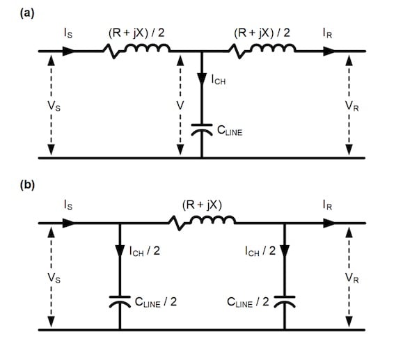
Figure 1. Current flowing through the shunt capacitance of the line is called charging current. (a). T-Model of a Transmission Line. (b). π-Model of a Transmission Line. Image used courtesy of Schweitzer Engineering Laboratories.
- Conductance (G) accounts for dielectric losses in the insulator and surrounding air. Although often negligible in overhead lines due to air’s high resistivity, conductance becomes significant in cables or polluted environments where leakage paths form over the insulation surface.
Impedance and Admittance Matrix for Multiphase Systems
In a multi-conductor (typically three-phase) system, impedance and admittance must be treated as matrices due to mutual effects. The per-unit-length impedance matrix [Z] and admittance matrix [Y] are defined as:
![]()
Each diagonal element includes self-impedance or self-admittance, while off-diagonal terms represent mutual interactions. Accurate modeling of these matrices is essential for line impedance calculation and fault analysis.
Impact of Conductor Geometry and Bundling
The physical configuration of conductors—including spacing, bundling, and transposition—affects the values of series and shunt parameters.
- Bundled conductors reduce the inductance and increase the capacitance due to the decrease in the geometric mean distance (GMD) between sub-conductors.
- Transposition of phases over the length of the line equalizes the mutual impedance effects and balances voltage drops across all phases.
For example, reducing the GMD by using bundled conductors in 500 kV lines helps decrease reactance, thereby improving power transfer capability and reducing corona losses.
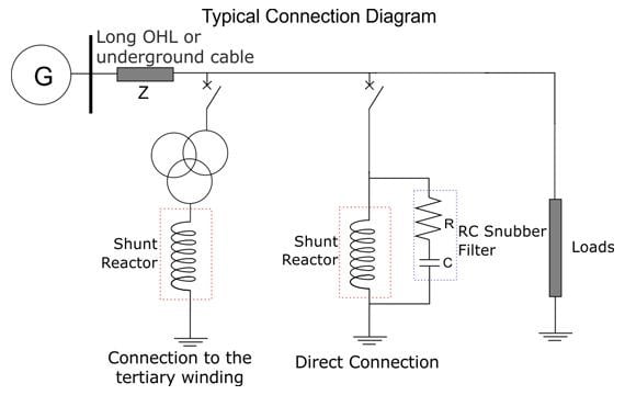
Figure 2.Transposition in a Transmission Line. Image used courtesy of poriyaan.in.
Real Power Losses Due to Conductor Resistance
In an AC transmission line, real (active) power losses primarily occur due to the ohmic resistance of the conductors. These are known as I2R losses, where current flowing through the series resistance dissipates energy in the form of heat. The expression for real power loss per phase in a three-phase line is given by:
$$P_{loss} = I^2 R$$
…where I is the RMS line current and R is the per-phase resistance of the transmission line over its total length. Since line resistance increases with temperature and frequency (due to skin effect), power losses can be substantial, especially over long distances or under high-load conditions.
Mitigating resistive losses involves using conductors with lower resistivity (for example, copper or aluminum), increasing the conductor cross-sectional area, and employing bundled conductors to reduce the effective AC resistance.
Voltage Drop Along the Line
Voltage drop in a transmission line results from both the resistive and inductive components of the line’s series impedance. In a simplified model, the per-phase voltage drop from sending end to receiving end is expressed as:
$$\Delta V = IZ = I(R + jX) = IR + jIX$$
Here, IR represents the resistive voltage drop which directly contributes to real power loss, and IX is the reactive voltage drop, causing a phase shift between current and voltage and affecting the voltage magnitude at the receiving end. In practical systems, this drop is further affected by the power factor of the load. For lagging power factor loads (common in inductive industrial applications), the voltage drop is more pronounced due to higher reactive power flow.
The magnitude of the receiving end voltage can be approximated using:
$$|V_R| \approx |V_S - I$$
Where VS is the sending end voltage and Z is the total line impedance. Voltage regulation becomes critical in maintaining system stability, particularly during peak load scenarios or faults.
Reactive Power and Its Effects on System Performance
Reactive power (Q), although it does not contribute to real energy transfer, plays a vital role in sustaining the electromagnetic fields necessary for energy conversion in AC systems. Reactive power in transmission lines arises from both:
- Line inductance (which consumes reactive power)
- Line capacitance (which generates reactive power)
The net reactive power balance significantly impacts voltage profiles and loadability of the transmission line. The reactive power transmitted over the line, assuming a lossless model, is:
$$Q = \big( \frac{V_R}{X} \big) \cdot \big( V_s \cos (\delta) - V_R \big)$$
where:
- VS and VR are the sending and receiving end voltages,
- X is the line reactance,
- δ is the power angle.
An excess of inductive reactive power leads to voltage drops, while excess capacitive reactive power (especially in light load or no-load conditions) causes overvoltages—a phenomenon known as the Ferranti effect in long lines.
Relation Between Power Losses and Reactive Flow
Reactive power flow indirectly contributes to real power losses. This is because the total current flowing through the line includes both real and reactive components. The total current I is given by:
$$I = \frac{S^*}{\sqrt{3} \cdot V } = \frac{P - jQ}{\sqrt{3} \cdot V }$$
Even if real power P remains constant, higher reactive power Q increases the current magnitude, which in turn increases I2R losses. Hence, managing reactive power is crucial for improving the overall transmission efficiency.
The power factor (PF), defined PF = cos (θ) = P/S, where S is the apparent power, is an important metric. A low power factor means higher currents for the same amount of real power, leading to more line losses and voltage drops.
Suppose we need to transmit 1000 kW of real power at 11 kV line-to-line with two different power factors:
Case 1: High Power Factor (PF = 1.0)
$$S = \frac{P}{\cos (\theta)} = \frac{1000}{1} = 1000 \text{ kVA}$$
$$I = \frac{1000 \times 10^3}{\sqrt{3} \cdot 11 \times 10^3 } = 52.5 \text{ A}$$
Case 2: Low Power Factor (PF = 0.7)
$$S = \frac{P}{\cos (\theta)} = \frac{1000}{0.7} = 1428.6 \text{ kVA}$$
$$I = \frac{1428.6 \times 10^3}{\sqrt{3} \cdot 11 \times 10^3 } = 75 \text{ A}$$
Now, comparing losses:
- At PF = 1: Ploss = 3 × (52.5)2 × R ≈ 8269R
- At PF = 0.7: Ploss = 3 × (75)2 × R ≈ 16875R
So, line losses double due to poor power factor, assuming the same resistance R.
Long-Distance Transmission and Reactive Compensation
In long-distance EHV (Extra High Voltage) or UHV (Ultra High Voltage) lines, where the capacitive and inductive reactances are non-negligible, the imbalance in reactive power leads to inefficient transmission. To reduce losses and maintain voltage profiles, utilities employ:
Shunt reactors to absorb excess capacitive reactive power during light loads
- Shunt capacitors to supply reactive power during heavy inductive loading
- FACTS devices for dynamic compensation
Thus, managing reactive power is not only about maintaining voltage stability but also about minimizing real power losses due to elevated line current levels.
Figure 3. Transmission line with Shunt Reactor Compensation. Image used courtesy of Hilkar.
Key Takeaways
Understanding the relationship between resistance, inductance, and capacitance in transmission lines is essential for ensuring reliable and efficient power delivery, particularly in modern high-voltage and long-distance systems.
These parameters directly impact power losses, voltage regulation, and reactive power behavior—factors that are critical for maintaining system stability, reducing operational costs, and meeting load demands without compromising power quality.
Effective management of these electrical characteristics enables grid operators to optimize conductor design, select appropriate compensation equipment, and implement advanced control strategies. This becomes increasingly vital as power systems evolve to accommodate fluctuating renewable sources, higher loads, and expanding transmission networks.
Make sure to check out Part 2 of this article series.
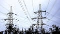
Featured image used courtesy of Adobe Stock (licensed)