Facebook
 Google
 GitHub
 Linkedin
Role of Thyristor-Controlled Series Capacitors in Power System Control
In this article, learn about the role of Thyristor-Controlled Series Capacitors (TCSC) in enhancing power system performance through dynamic impedance control.
Here in Part 6, and the final part, of our Transmission Line Losses and Efficiency Optimization article series, we look at Thyristor-Controlled Series Capacitors (TCSCs). TCSCs are used in power systems to dynamically adjust the series impedance of transmission lines, enabling precise control over power flow and improving system stability. By varying the thyristor firing angle, the device can shift from capacitive to inductive behavior, allowing real-time modulation of transmitted power and damping of oscillations.
This capability helps balance line loadings, reduce transmission losses, and enhance transient stability during faults. Additionally, when used with other FACTS devices like STATCOMs, TCSC contributes to more efficient voltage profiles, mitigates congestion, and supports deferral of infrastructure expansion by optimizing the use of existing transmission assets.
TCSC: Dynamic Impedance Control
The Thyristor-Controlled Series Capacitor (TCSC) dynamically modifies the series impedance of a transmission line through a hybrid configuration: a fixed series capacitor (C) shunted by a thyristor-controlled reactor (TCR). By adjusting the thyristor firing angle α, the equivalent impedance of the TCSC can be modulated from capacitive to inductive, depending on the relative dominance of the capacitive and inductive branches.
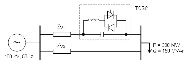
Figure 1. Electrical network with TCSC. Image used courtesy of EEA Journal.
When the thyristors are blocked (α = 180 degrees), the inductor is non-conductive, and the TCSC operates as a fixed series capacitor with reactance:
$$X_C = \frac{1}{\omega C}$$
As the thyristors begin to conduct at firing angles α < 180 degrees, the inductor introduces a time-varying voltage component that partially cancels the capacitor’s voltage, resulting in a reduced net capacitive reactance. The fundamental component of the TCSC’s equivalent reactance XTCSC(α) is given by:
$$X_{TCSC}(\alpha) = X_C \left[ \frac{1}{1 - \left(\frac{X_C}{X_L}\right) \cdot F(\alpha)} \right]$$
where:
- XL = ωL is the reactor’s inductive reactance
- F(α) is a nonlinear function of the thyristor conduction angle, derived from Fourier analysis of the periodic voltage waveform
At a critical firing angle, a parallel resonance condition occurs when the inductive and capacitive reactances cancel each other out. This can cause rapid excursions in impedance and is avoided in practice through protective firing angle limits.
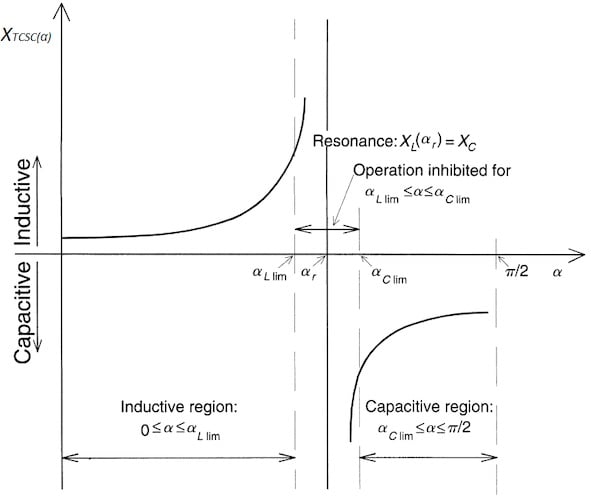
Figure 2. TCSC reactance vs. firing angle characterizes. Image used courtesy of PSMA Consulting Services.
Modulation of Line Power Flow Through Impedance Control
TCSC enables real-time regulation of power transfer by adjusting the line’s effective series impedance. The classical power flow expression between two buses connected via a line of total reactance X is:
$$P = \left( \frac{V_1 V_2}{X} \right) \sin (\delta)$$
Here, V1 and V2 are the sending and receiving end voltages, δ is the power angle between them, and X = Xline - XTCSC is the net reactance after compensation. A decrease in X leads to an increase in transmitted power for the same angle δ, making TCSC a powerful tool for redistributing active power flows across transmission corridors.
Importantly, because the TCSC can vary its compensation continuously (for example, 0–70% of line reactance), it enables adaptive power flow control. This makes it suitable for dynamic applications like:
- Preventing overloads during N-1 contingencies
- Coordinating flows in looped systems
- Improving OPF outcomes by relieving congestion on critical lines
In meshed networks, this controllability is particularly advantageous for loop flow mitigation, allowing operators to fine-tune line loadings without redispatching generation or shedding load.
Dynamic Damping and Transient Stability Enhancement
TCSC also provides important benefits for electromechanical damping and transient stability, which can be quantified via small-signal analysis of the generator–infinite bus model. The electrical power output of a generator is affected by the transfer reactance X, and its derivative with respect to rotor angle δ, known as synchronizing torque coefficient, is critical for maintaining stability:
$$\frac{\partial P}{\partial \delta} = \left( \frac{V_1 V_2}{X} \right) \cos (\delta)$$
A lower X increases this derivative, thereby improving the synchronizing torque and enhancing damping of rotor angle oscillations. TCSC controllers exploit this property through Power Oscillation Damping (POD) mechanisms. These typically use input signals like generator speed deviation Δω or line current deviation ΔI, processed through lead-lag filters and gain blocks to produce a reference impedance modulation ΔXTCSC that actively damps the oscillation.
In faulted conditions, such as line outages or three-phase faults followed by clearing, the generator rotor angle can experience significant excursions. By temporarily decreasing X during the first swing, the TCSC increases power transfer, helping the generator remain synchronized. Once the transient passes, the controller returns the impedance to nominal levels, maintaining long-term equilibrium without overloading the line.
Deployment in Meshed Transmission Networks
Meshed systems present particular challenges due to the natural tendency of power to flow along paths of least impedance. In such grids, some lines may become overloaded while others are underutilized, even when total system generation and demand are balanced. TCSC addresses this by providing real-time controllability of individual line impedances, thereby allowing grid operators to enforce desired power sharing across parallel paths.
From a control perspective, TCSC devices can be integrated into higher-layer EMS applications such as security-constrained optimal power flow (SCOPF), where their dynamic impedance settings are treated as control variables. Advanced installations also incorporate TCSCs into wide-area damping control systems, where synchrophasor-based signals are used to detect inter-area oscillations and initiate coordinated impedance modulation across the network.
Despite its advantages, the deployment of TCSC requires careful coordination, especially in corridors with multiple compensated lines. Uncoordinated or aggressive control action can introduce modal interactions or interfere with generator AVR and PSS responses. As such, modern implementations often use model predictive control (MPC) or decentralized control architectures to ensure robust performance under multiple operating scenarios.
Relationship Between Power Flow and Transmission Losses
In high-voltage power systems, a significant portion of real power losses occurs due to conductor heating, quantified by the well-known Joule loss expression:
$$P_{loss} = I^2 R$$
where I is the magnitude of the line current and R is the resistance of the conductor. For a given power transfer P across a line with impedance , the current magnitude is determined by:
$$I = \frac{P}{V \cos (\theta)}$$
Assuming constant voltage V and small angle θ, any reduction in current flow directly reduces I2R losses. Thus, loss minimization strategies in meshed systems often target current redistribution rather than reduction of total power transfer.
This is precisely where FACTS devices—especially series and shunt compensators—introduce strategic leverage. By dynamically adjusting line impedance (via TCSC) or injecting controlled reactive power (via STATCOM or SVC), these devices reshape power flows and equalize line loadings across parallel corridors. This optimized load sharing allows more efficient use of available transmission capacity, lowering the current in overloaded paths and thereby minimizing resistive losses system-wide.
Mechanism of Load Sharing and Thermal Relief
In a simplified two-path network connecting the same source and load regions, power flow divides inversely in proportion to the series impedance of each path. For two lines with impedances Z1 and Z2, the active power ratio can be approximated by:
$$\frac{P_1}{P_2} \approx \frac{Z_1}{Z_2} $$
This implies that even modest impedance differences can result in uneven power flows, with one line potentially operating near thermal limits while the other remains underutilized. FACTS devices intervene by modifying the apparent impedance of one or both lines, shifting the power ratio toward a more balanced distribution.
For example, inserting a TCSC into Line 1 allows dynamic reduction of its reactance XTCSC, thereby increasing its power flow and relieving Line 2. The result is not only improved thermal margin but also a reduction in system-wide losses, since high-loss paths are bypassed. This capability is particularly effective during N-1 contingencies, where system topology shifts suddenly and loadings must be rebalanced quickly to prevent cascading outages.
Congestion Management and Deferral of Transmission Expansion
A further benefit of FACTS-based load flow control lies in congestion management and investment deferral. In congested grids, particularly those with high renewable penetration, line overloads can arise not from total generation-demand imbalance, but from geographical and topological mismatch. FACTS devices mitigate these bottlenecks by exploiting existing right-of-way more efficiently, pushing more power through underloaded corridors and relieving critical links.
This dynamic capability extends the useful life of aging transmission assets and delays the need for new line construction, which is often constrained by regulatory, environmental, or social licensing hurdles. By alleviating the immediate need for capacity expansion, FACTS technologies deliver capex savings and timeline relief, allowing utilities to plan grid reinforcements on longer, more strategic horizons.
Moreover, the granular controllability provided by FACTS devices enables integration into real-time control schemes such as security-constrained economic dispatch (SCED) or remedial action schemes (RAS). In these frameworks, FACTS act not only as reliability enhancers but also as market enablers, allowing more efficient dispatch of generation while respecting transmission constraints—ultimately reducing locational marginal prices (LMPs) and system operation costs.
Economic Perspective: Loss Reduction vs. Installation Cost
While FACTS devices represent a nontrivial capital expenditure, the economic benefit of reduced losses is quantifiable and often justifies the investment over a medium time horizon. For example, if a STATCOM installation leads to a net annual loss reduction of 25 GWh in a region with marginal generation cost of $60/MWh, the savings alone amount to $1.5 million/year.
When factored alongside avoided curtailment, congestion relief, and deferred upgrades, the return on investment becomes compelling—especially under performance-based regulatory frameworks that reward loss minimization or voltage compliance.
Advanced cost-benefit analysis tools now incorporate dynamic models of FACTS behavior under real operating profiles, enabling planners to assess multiple deployment scenarios with realistic load and generation variability.
This is particularly valuable in systems with high renewables, where FACTS can substantially reduce the curtailment of zero-marginal-cost energy sources by unlocking constrained transmission paths.
Key Takeaways
TCSC and other FACTS technologies play a vital role in addressing the operational and planning challenges of modern power systems, especially in the context of increasing renewable integration, complex meshed networks, and constrained transmission corridors. Their ability to dynamically control power flow, enhance transient and small-signal stability, and reduce system losses makes them essential tools for maintaining grid reliability under stressed conditions.
Moreover, their application in congestion management, load balancing, and infrastructure deferral enables utilities to extract maximum value from existing assets while supporting long-term grid modernization goals. As power systems evolve, these devices will continue to be key enablers of secure, flexible, and cost-effective transmission networks.
Featured image used courtesy of Adobe Stock (licensed)