Facebook
 Google
 GitHub
 Linkedin
Transfer Mold IPM Family “SLIMDIP” with 5A/15A 600V RC (Reverse Conducting) IGBT in a Compact Package
This article highlights Mitsubishi Electric Dual-In-line Package (DIP) Intelligent Power Module SLIMDIP with ratings of 5A and 15A/600V in a compact package.
A very compact Dual-In-line Package (DIP) Intelligent Power Module SLIMDIP with ratings of 5A and 15A/600V has been developed employing Reverse Conducting (RC) IGBT chip technology. This technology integrates the required freewheeling function for inductive loads into the developed RC-IGBT chip and makes the diode that is usually connected antiparallelly to a conventional IGBT redundant.
As a consequence the employment of reverse conducting IGBT chips save space and that resulted in the new package of the SLIMDIP being designed very compact. The SLIMDIP provides protection functions for under voltage, short circuit and over temperature as well as a linear output signal for the case temperature. The interface circuit of the SLIMDIP is 3.3V to 5V compliant and the pin terminal assignment simplifies the printed circuit board layout design.
Variable speed Inverters
Variable speed Inverters are increasingly used to drive small motors aiming to increase the efficiency of motor control systems.
This development has become visible also in the white goods and small fan and pump application fields that are driven by small motor drives with a rating of up to about 2,2kW. Responding to this demand the continuously further developed Super Mini DIPIPM has been developed in 2004 already and has set package standards in this specific market segment. Now a further technology step has been realized and a new smaller transfer mold IPM has been developed, actually mainly addressing the white goods application market segment such as washing machines and air-conditioner.
SLIMDIP significantly improves
This new SLIMDIP significantly improves compactness, power density, efficiency and controllability of systems. Today, two devices have been developed for the two main existing application segments: A SLIMDIP “small” (“S”) with a typical collector current rating of 5A is mainly addressing the power requirements of typical European household washing machines, e.g. driven by a motor of around 750W of shaft power or smaller applications and the SLIMDIP “large” (“L”) with a typical collector current rating of 15A focuses on the higher power demand of air conditioners or drives for professional heavy-duty washing machines.
Since these applications usually do not use an isolated interface between the IGBT driver stage and the microprocessor the SLIMDIP family is equipped like all transfer mold IPMs with the latest generation of High Voltage Integrated Circuits (HVIC) to drive and to protect the power stage. Simplifying the peripheral circuit the SLIM DIP has robust bootstrap diodes and corresponding current limiting resistors for the bootstrap operation integrated into the package.
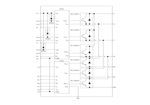
Figure 1: Shows the internal block diagram with RC-IGBT, the LVIC and HVIC and the integrated bootstrap circuitry.
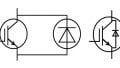
RC-IGBT Merits
The RC-IGBT technology provides merits in the fabrication process of the SLIMDIP mainly in the assembling process since it is simpler with a half power-chip-die bonding and without Al wire-bonding from IGBT to the diode. The availability of a freewheeling function of the RC-IGBT chip itself, e.g. without an externally connected dedicated diode is saving module space and provides cost-efficient and compact package design.
Package Design
This new SLIMDIP package is following the DUAL INLINE concept known from the version 6 Super Mini DIPIPM but with further development of the lead frame and integrated functions. The compact package of only 18.8mm x 32.8mm has got control terminals arranged in zig-zag shape providing sufficient clearance between the holes, the outer annular ring avoiding expensive printed circuit board fabrication processes like fine pattern structures with the utilized pitch etc. The control and power terminal structure and arrangements are indicated in Figure 2.
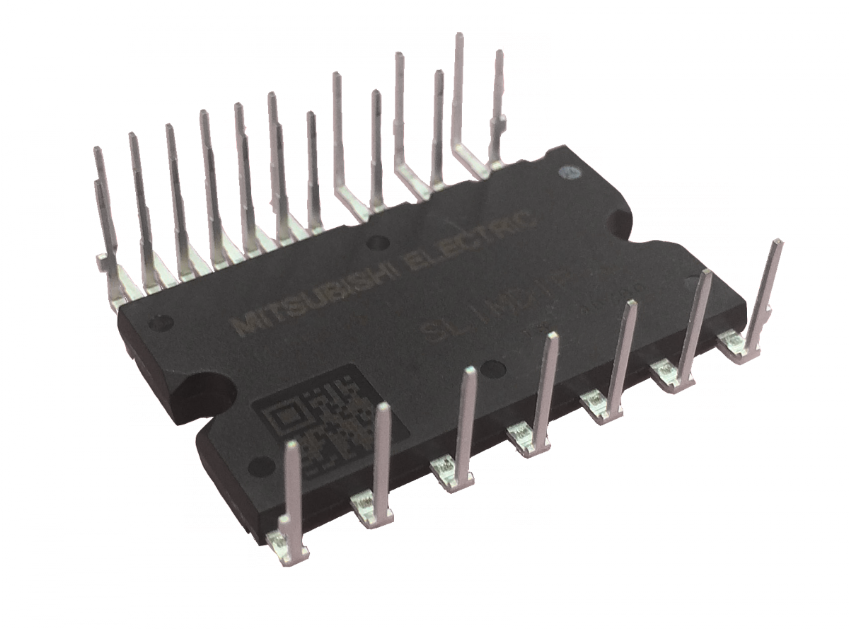
Figure 2: Photo of the SLIMDIP
The arrangement of the terminals has been further improved versus the Super Mini DIPIPM version construction since the bootstrap capacitors have dedicated terminals assigned and a crossing of PCB traces under the footprint of the SLIMDIP to the corresponding output terminal is not required anymore.
Also, the improved lead frame pin terminal assignment simplifies the design of a printed circuit board and total cost-optimized designs targeting the realization of the complete motor drive on only a single-sided printed circuit board become possible easier. As shown in this figure, the SLIMDIP provides an open emitter structure that permits the acquisition of phase currents when all low side IGBTs are turned ON, e.g. during the lower zero vector of the Pulse Width Modulation (PWM). These shunt resistors if selected as surface-mounted device ideally fit under the footprint of the SLIMDIP and would reduce the stray inductance of the complete DC-link construction accordingly.
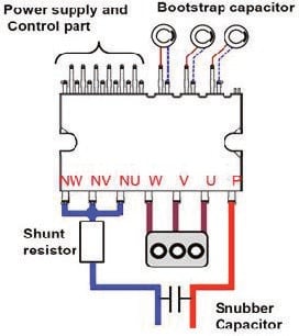
Figure 3: Shows the improved pin terminal layout
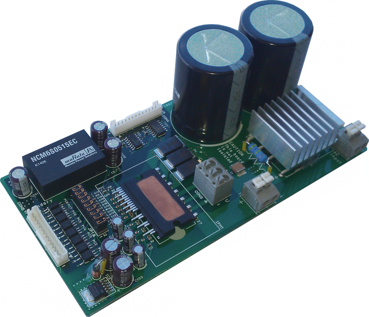
Figure 4: Evaluation board
Performance Comparison
Besides the improvement of the construction of the new SLIMDIP housing, a set of performance extensions have been reached with this newly developed device. Indeed, the maximum case temperature has been specified higher: While previously the Super Mini DIPIPM package has been specified for a maximum of 100°C of case temperature, the new SLIMDIP’s maximum case temperature has been extended to 115°C.
As a consequence of this extended specification, the internal over-temperature (OT) threshold has been adjusted accordingly now starting at 115°C. Concerning the isolation voltage, the specification has been increased by over 500Vrms from the 1500Vrms that have been specified for the Super Mini DIPIM to the level of 2000Vrms for the SLIMDIP. Along with the more compact dimensions of the case these improvements have been summarized in table 1 showing the extended specification of the SLIMDIP.
Protection Functions
The protection of the power stage is an essential task of an IPM and a dedicated circuitry is employed in the control part or both the Low Voltage Integrated Circuit (LVIC) and the High Voltage Integrated Circuit (HVIC) that contains the level shifting function.
Under-voltage protection, short circuit protection is the standard protection functions integrated in the transfer mold IPMs, but as innovation, the newly developed SLIMDIP contains a thermal protection function “over-temperature protection,” and issues at the same time an accurate temperature proportional signal “VOT” that allows taking action when the thermal limit, e.g. the over-temperature threshold is close in order to avoid a sudden interrupt of the drive operation.

Table 1: Extended specification of the SLIMDIP
Evaluation Platform
The features and the new extended functionality of the SLIMDIP can be verified by the developed evaluation board. The photo shows the evaluation platform employing the input rectification circuit the bulk DC-link capacitors a 15V/5V DC-DC converter stage and isolated input circuitry for a safe connection to a microprocessor board.
The board uses clamp connectors for the power connections like AC in, 3~ motor connector etc. which provide a quick connection of cabling to this evaluation board. On the control terminal side, a standard self-locking JST connector type is foreseen to connect control signals safely to the evaluation board.
About the Author
Marco Honsberg received his engineering degree at Bergische University Wupperta and MBA at FOM University of Economics & Management. He worked as a part of Mitsubishi Electric Europe BV Business Development.
Teruaki Nagahara worked at Mitsubishi Electric Corporation that has been at the forefront of Japan’s technical ingenuity and product innovation from an electric fan for consumer use continued to create a long list of “firsts” and groundbreaking new technologies that have shaped its business fields all around the world.
Reference
- S. Noda, K. H. Hussein, S. Yamada, G. Majumdar, T. Yamada, E. Thal, and G. Debled “A novel super compact intelligent power module,” in Proc. 1997 PCIM Europe,Nurnberg, Germany, Power Conversion vol.34, pp. 1-10.
- K. Satoh, T. Iwagami, H. Kawafuji, S. Shirakawa, M. Honsberg, E. Thal:” A new 3A/600V transfer mold IPM with RC (Reverse Conducting) –IGBT”, 2006 PCIM Europe
- H. Iwamoto, E. Motto, J. Achhammer, M. Iwasaki, M. Seo,T. Iwagami, “New Intelligent Power Module for Appliance Motor Control”, 2000 PCIM Europe,
- M. Iwasaki, T. Iwagami, M. Fukunaga, X. Kong, H.Kawafuji, G. Majumdar, “A New Version Intelligent Power Module for High Performance Motor Control”, 2004 PCIM China,
- T. Sasaki, H. Takao, T. Shikano, S. Fujita, D. Nakajima, T.Shinohara, “Development of High Current Transfer-mold type Power Module with High Heat-cycle Durability”, 2004 ISPSD Kitakyushu,
- H. Takahashi, A. Yamamoto, S. Aono, T. Minato, “1200V Reverse Conducting IGBT”, 2004 ISPSD Kitakyushu
This article originally appeared in the Bodo’s Power Systems magazine.