Facebook
 Google
 GitHub
 Linkedin
Calculating Power In RL And RC Circuits
This article will discuss the fundamentals of power in RL and RC circuits, including how power is calculated and the different types of power associated with these circuits.
Power in RL and RC circuits can change over time due to transient effects, such as charging or discharging inductors or capacitors. Therefore, analyzing the power behavior requires considering instantaneous and steady-state power, as well as reactive power due to energy storage and release by inductors or capacitors.
RL Circuit Power
In a series circuit consisting of inductance and resistance, the current lags the voltage by an angle (ɸ) that is less than 90°. Figure 1 shows typical voltage and current waveforms for an RL circuit, along with the power waveform in the circuit. The power waveform is derived by multiplying together instantaneous values of voltage and current.
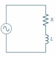
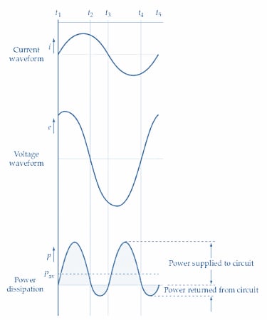
Figure 1. The power waveform for an RL circuit can be derived from the voltage and current waveforms. Some power is dissipated in the resistance, so the positive and negative portions of the power waveform are unequal. Image used courtesy of Amna Ahmad
During the period from t1 to t2, both i and e are positive quantities, so power p remains positive throughout that time. From t2 to t3, i is positive, and e is a negative quantity; consequently, the product of i and e is negative, and the power waveform is below the zero line. After t3, the current and voltage are both negative until t4. Because -e-i is a positive quantity, the power is positive again from t3 to t4.
The power waveform clearly shows that more positive power than negative power is supplied to the circuit. This is to be expected because power is dissipated in the resistance, but the average power supplied to the inductance remains at zero. The average power supplied to the circuit can be represented by the dashed line shown on the power waveform.
Now consider the phasor diagram for a series RL circuit, as illustrated in Figure 2. The current I is shown lagging the applied voltage E by the angle ɸ. The voltage across the resistance (ER) is in phase with I, so ER also lags E by angle ɸ. The voltage across the inductance is EL, and it leads the current at an angle of 90°. The phasor sums of ER and EL gives the supply voltage E, as illustrated.
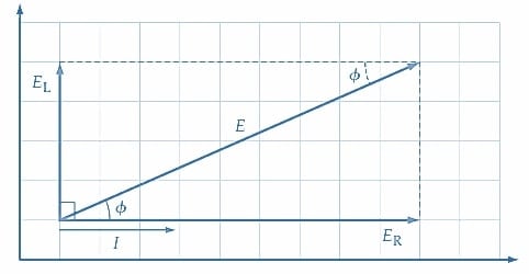
Figure 2. Phasor diagram for an RL series circuit. Image used courtesy of Amna Ahmad
Because power is dissipated only in the resistive component, the circuit power is \(P=I\times(voltage\,in\,phase\,with\,I),or\,P=EI\,cos\,cos\Phi\).
The true power dissipated in the RL circuit is, of course, the power dissipated in the resistor. So, true power is
\[P=E_{R}\times I\]
and from Figure 2
\[E_{R}=E\,cos\,cos\Phi\]
Giving
\[P=(E\,cos\,cos\Phi)\times I\]
Or true power is
\[P=EI\,cos\,cos\Phi(1)\]
The reactive power is the product of the inductive voltage and current, EL and IL.
From Figure 2
\[E_{L}=E\,sin\,sin\Phi\]
And
\[I_{L}=I\]
So
\[Q=EI\,sin\,sin\Phi(var)(2)\]
If the supply voltage E and the measured current I in an RL circuit are multiplied together, the product is neither the true power nor the reactive power. However, it does give a quantity that appears to be the power supplied to the circuit. The term apparent power (S) is applied to this quantity, and units of apparent power are volts-amps (VA):
Apparent power
\[S=EI(3)\]
where S is the apparent power, and E and I are rms values of supply voltage and current.
Example 1
In a series RL circuit supplied with 50 V, the current is measured as 100 mA with a phase angle of 25° (Figure 3). Calculate the apparent, reactive, and true power supplied to the circuit.
Solution
Equation 3
\[S=EI\,volt-amp=50V\times100mA=5VA\]
Equation 2
\[Q=EI\,sin\,sin\Phi\,var=50V\times100mA\times{\Big(}sin\,sin\,25\degree{\Big)}\approx2.1var\]
Equation 1
\[P=EI\,cos\,cos\Phi watts=50V\times100mA\times{\Big(}cos\,cos\,25\degree{\Big)}\approx4.5W\]
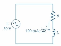
Figure 3. Circuit for Example 1. Image used courtesy of Amna Ahmad
RC Circuit Power
When the current and voltage waveforms in a series RC circuit are employed to derive the waveform of the power supplied (Figure 4), it is seen that a similar result is obtained as in the case of the RL circuit. The average Power supplied to the circuit is a positive quantity, and this represents the power dissipated in the resistance. The phasor diagram for the RC circuit, as shown in Figure 5, gives the same equations for true power, reactive power, and apparent power as those derived for the RL circuit.
The power supplied to parallel RC and RL circuits can also be resolved into true power, reactive power, and apparent power components. Using the supply voltage and current and the current-voltage phase angle, Equations 1, 2, and 3 are just as valid for parallel circuits as for series circuits.
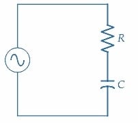
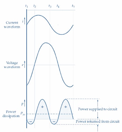
Figure 4. The power waveform for an RC circuit can be derived from the voltage and current waveforms. The positive and negative portions of the power waveform are unequal because some power is dissipated in the resistance. Image used courtesy of Amna Ahmad
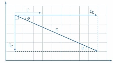
Figure 5. Phasor diagram for an RC circuit. Image used courtesy of Amna Ahmad
Because power is dissipated only in the resistive component, the circuit power is \(P=I\times(voltage\,in\,phase\,with\,I),\,or\,P=EI\,cos\,cos\Phi\).
Example 2
A series circuit consisting of R =1.2 kΩ and C=0.1 µF is supplied with 45 V at a frequency of 1 kHz (Figure 6). Determine the apparent power, true power, and reactive power in the circuit.
Solution
\[X_{C}=\frac{1}{2\pi fC}=\frac{1}{2\pi\times1kHz\times0.1\mu F}=1.59k\Omega\]
\[|Z|=\sqrt{R^{2}+X^{2}_{C}}=\sqrt{(1.2k\Omega)^{2}+(1.59k\Omega)^{2}}=1.99k\Omega\]
\[\Phi=tan\,\^{} \,(-1)\frac{X_{C}}{R}=tan\,\^{}\,(-1)\frac{1.59k\Omega}{1.2k\Omega}\approx53\degree\]
\[|I|=\frac{E}{Z}=\frac{45V}{1.99k\Omega}=22.6mA\]
Apparent power
\[S=EI=45V\times22.6mA\approx1VA\]
True power
\[P=EI\,cos\,cos\Phi=45V\times22.6mA\times{\Big(}cos\,cos\,53\degree{\Big)}=0.61W\]
Reactive power
\[Q=EI\,sin\,sin\Phi=45V\times22.6mA\times{\Big(}sin\,sin\,53\degree)=0.81\,var\]
Because the true power is the power dissipated in the resistor, it can also be calculated as I2 R.
\[P=I^{2}R=(22.6mA)^{2}\times 1.2k\Omega=0.61W\]
Reactive power can be calculated as I2XC.
\[Q=I^{2}X_{C}=(22.6mA)^{2}\times1.59k\Omega=0.81var\]
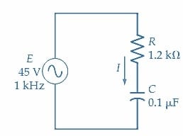
Figure 6. Circuit for Example 2. Image used courtesy of Amna Ahmad
Example 3
A parallel impedance circuit with a 33 V supply has a current of 75.2mA∠10.5°. Calculate the apparent power, true power, and reactive power.
Solution
Equation 3
\[S=EI=33V\times75.2mA\approx2.5VA\]
Equation 1
\[P=EI\,cos\,cos\Phi=33V\times75.2mA\times cos\,cos\,10.5\degree=2.44W\]
Equation 2
\[Q=EI\,sin\,sin\Phi=33V\times75.2mA\times sin\,sin\,10.5\degree=0.45var\]
Key Takeaways of RL and RC Circuits
In both RL and RC circuits, the power dissipated or stored can be calculated using mathematical formulas that take into account the circuit parameters, such as resistance, inductance, capacitance, and voltage or current values. Analyzing power in RL and RC circuits is essential for designing efficient circuits and ensuring safe and reliable operation in various electronic applications.
To catch up on the other articles in this series, follow these links:
- Understanding RL Circuit Operation and Time Constant
- Understanding RC Circuit Operation and Time Constant
- Examining Series RL Circuit Behavior
- Series RC Circuit Analysis
- Determining Series RLC Circuit Resonance Frequency
Featured image used courtesy of Adobe Stock