Facebook
 Google
 GitHub
 Linkedin
More Power by RC-IGBT Technology
Fuji Electric introduces a new product in a well-known package to increase the output power of IGBT modules by applying “RC-IBGT” (RC stands for Reverse Conducting) technology for high-power applications. The PrimePACK™3 and 3+ are suitable for high power applications in the common 1,700 and 1,200 V ratings.
The market demand for power semiconductors has been increasing for years and is requiring a miniaturization of power conversion systems, a reduction of cost and an increase in performance. Such a gain in performance is achieved by increasing the output power in a given package size, which goes hand-in-hand with elevated temperatures within the system. This results in a risk of a shorter product lifetime, due to a reduced number of power cycles at elevated temperatures.

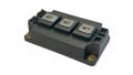
Figure 1: Outline of a PrimePACK™3+ with the two characteristic output terminals. Image used courtesy of Bodo's Power Systems.
Due to this phenomena, Fuji Electric accepted the challenge to develop chips and packages, which can withstand these higher performance levels, and presented the 7th generation, the “X series”, IGBT module technology some years ago. It combines high power density with high reliability by reducing the power dissipation. Furthermore, Fuji Electric developed the RC-IGBT technology, which integrates IGBT and FWD in a single chip. This enables not only a reduction of chip amount and chip area by keeping the same level of rated current, even higher currents can be realized.
This results in an increase of the rated current in the same package size and smaller power dissipation by combining the X series technology with the RC-IGBT technology. The reliability of the RCIGBT portfolio exceeds the level of conventional IGBT modules. In this article, Fuji Electric presents the PrimePACK™3+ with a nominal voltage of 1,700 V (and 1,200 V) for industrial applications.

Figure 2: Schematic diagrams of the X series RC-IGBT and equivalent circuits. Image used courtesy of Bodo's Power Systems.
RC-IGBT Technology
The RC-IGBT technology combines patterns of IGBT and FWD regions with a suitable structure on a single chip. The portion of active area to the total chip area increases because the chip’s edge termination decreases relatively and generates more space in the module housing for bigger chips for an even higher output current. Another benefit is that the extended chip area reduces the thermal resistance between junction and case, Rth(j-c), drastically.
The bigger chip area acts like a thermal buffer zone: the generated heat in the IGBT region is transferred also to the FWD region and vice versa. Thus, the I²t capability of the RC-IGBT is 3.8 times higher compared to the predecessor V series generation.

Figure 3: I2t capability at 150 deg.C. Image used courtesy of Bodo's Power Systems.
The switching waveforms (Figure 4-6), taken at an elevated temperature of 150 deg C, underline the smooth operation of the RC-IGBT chips. The overcurrent and overvoltage peaks are tidy and oscillations occur on a very limited level. The tail current is quite small and prevents the existence of a big energy loss during turn-off.

Figure 4: Switching waveform for turn-on at 150 deg C. Smooth switching of VCE and IC without bigger oscillations. Image used courtesy of Bodo's Power Systems.

Figure 5: Switching waveform for turn-off at 150 deg C. The small tail current prevents the existence of a big energy loss. Image used courtesy of Bodo's Power Systems.

Figure 6: Switching waveform for reverse recovery at 150 deg C, with very low oscillations. Image used courtesy of Bodo's Power Systems.
Some examples of the proper RC-IGBT design-in and use depict the advantages:
A large-scale grid-connected photovoltaic system, where IGBT modules are connected typically in parallel for enlarging the output current. This topology requires usually much system space and a well-planned electrical setup with lowest current imbalances. PV systems operate normally at relatively constant power. In cases where two 1,400 A PrimePACK™s were used in the past, they can now be replaced with a single RC-IGBT module rated for 2,400 A, thus reducing the footprint by 50%. Simulations and use-in-field experience show and underline the benefits of this technology leap.
A high-power Drive system has a low output frequency during the motor start-up period. That is the most critical phase, since the load prevails on a single chip for a relatively long time. The resulting high temperature swings cause thermal stress on the die attached bonding wire connections and eventually decrease the power cycling lifetime. By applying RC-IGBT technology and its bigger relative chip area, these temperature swings are strongly reduced, which results in a longer lifetime. If such an application has two V series (6th generation IGBT) modules in parallel use, they can be exchanged with a single RC-IGBT module of the X series, which increases the lifetime.
In Wind power applications, the input wind power is transformed twice by some power electronics. On The generator side, an inverter converts the rotation of the wind turbine which provides AC electric power, into DC electric power. The turbine rotation starts slowly and the high load stresses the IGBT and FWD to a high extent. RC-IGBT chips would prevent these high temperature swings. On the grid side, the electrical power is converted back to AC electric power and is fed into the grid network. Both sides need to fulfill different roles because the functions are also different. However, the need for higher performance unites those AC/DC and DC/AC converters. The RC-IGBT technology helps to increase the system’s output current to 165% of previous V series technology solutions.
The operation comparison of a 1,800 A 7th gen IGBT module with a 2,400 A RC-IGBT module underlines the longer lifetime of the module with RC-IGBT technology. Due to the smaller temperature swings at the same output current, the lifetime is increased vastly.

Figure 7: Calculation conditions: Io=Vari., fc=3kHz, fo=50Hz, Vcc=600V, pf=0.9, m=1.0, RG=+0.22/-0.22Ω(X), +1/-1Ω(V), Rth(s-a)=0.006K/W, Rth(c-s)=0.0014K/W (with 3W thermal grease), Ta=50deg.C. Calculation results of the relationship between IGBT Tvj(max) and Io during continuous operation of X series module with RC-IGBT. Image used courtesy of Bodo's Power Systems.

Figure 8: Increasing output frequency pattern and temperature swing ΔTvj during motor start-up. (top) Calculation conditions: Io=Vari., fc=3kHz, fo=1Hz, Vcc=600V, pf=0.9, m=0.01, RG=+0.22/-0.22Ω(X), +1/-1Ω(V), Rth(s-a) = 0.006K/W, Rth(c-s) = 0.0014K/W (with 3W thermal grease), Ta=50deg.C, low-frequency start-up to continuous condition. (bottom) Image used courtesy of Bodo's Power Systems.
Another approach in utilizing the RC-IGBT PrimePACK™ is to achieve smaller footprints by replacing 16 pieces of a 600 A Dual XT modules with four 2,400 A RC-IGBT PrimePACK™s. Besides the fewer amount of driver units, which makes the system easier to control, the footprint also shrinks to only 40% of the initial system size. This downsizing trend will be more common in the future with the increased lineup of various RC-IGBT packages.


Figure 9: Comparison of junction temperature swing curves of a common 7th gen X-series 1800A module and a RC-IGBT 2400A module also using a 7th gen X-series IGBT. The RC-IGBT achieves a smaller temperature increase at the same output current. Calculation conditions: Io=Vari., fc=3kHz, fo=5Hz, Vcc=1200V, pf =-0.9, m=1, Standard RG, Rth(sa)=0.0047oC/W, Rth(c-s)=0.0014°/W (with 3W thermal grease), Ta=35°C. (top) The power cycle capability curve comparison shows the increase of statistical expected lifetime of the 2400A RC-IGBT. (bottom) Image used courtesy of Bodo's Power Systems.

Figure 10: Line-up of X series IGBT modules, also including the RC-IGBT technology in comparison to the predecessor V series. Image used courtesy of Bodo's Power Systems.
Fuji Electric’s PrimePACK™ portfolio is designed for Industrial application and provides up to 2,400 A rated module current in the 1,700 and 1,200 V classes. This is an increase of 33% of nominal output power compared to the conventional X series technology. Since handling currents of 2,400 A is challenging due to the generated heat in the output terminal, the PrimePACK™3+ package with two output terminals was chosen.
The increased output power of RC-IGBT technology contributes to the improvement of the performance of power conversion systems. Realizing higher currents within the same footprint supports the ongoing miniaturization of systems. Fuji Electric offers this technology in the PrimePACK™3+ to meet the market demands and strives to realize a safe, secure and sustainable society.
Note: PrimePACK™ is registered Trademark of Infineon Technologies AG, Germany
This article originally appeared in Bodo’s Power Systems magazine.