Facebook
 Google
 GitHub
 Linkedin
Traction Inverter Trends: Transfer Molded Modules
Transfer molded modules could meet new BEV requirements regarding power handling capability and electrical and thermal performance.
This article is published by EEPower as part of an exclusive digital content partnership with Bodo’s Power Systems.
The traction inverter is the heart of the e-mobility revolution. It is responsible for electrical propulsion and vehicle performance. Carmakers demand extremely high performance from both electrical and thermal aspects, compelling semiconductor companies to improve technology, including transitioning from standard silicon to silicon carbide and introducing new materials and cooling systems.
Traction Inverter Trends and New Requirements
The key elements of electrical traction are the e-motor and the traction inverter. Both components are significantly impacted by requirements for efficiency, compactness, car mileage, and thermal management.
![]()
Figure 1. Main requirements for the new BEV. Image used courtesy of Bodo’s Power Systems [PDF]
To increase the peak power of BEVs and improve efficiency, there is a shift from 400 V battery voltage to 800 V (Figures 1 and 2). Higher battery voltage reduces charging time and copper losses in the wires, which also helps reduce conduction losses in the inverter’s power stage.
Table 1. Current and bus voltage for a 400 kW inverter
| Current level for different bus voltage for 400 kW peak power | ||
| Vbattery (V) | 400 | 800 |
| IDC (A) | 1000 | 500 |
Conduction losses are predominant in such applications and have a quadratic relationship with the current. Alongside increasing bus voltage, significant research and development are focused on improving the dimensions of the traction inverter to make it lighter and more compact. This is achieved through new power module attachments to the heatsink, such as silver sintering, new materials, and new package concepts.
![]()
Figure 2. Principal trends for e-motor and traction inverter. Image used courtesy of Bodo’s Power Systems [PDF]
Half-Bridge Molded Modules
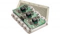
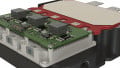
To address market challenges, STMicroelectronics is developing a new family of molded half-bridge modules with single-side and double-side cooling, addressing 750 V and 1200 V breakdown classes with a current range of up to 650 A (Figures 3 and 4).
![]()
Figure 3. Key features of the new half-bridge molded modules. Image used courtesy of Bodo’s Power Systems [PDF]
![]()
Figure 4. Benefits of molded modules. Image used courtesy of Bodo’s Power Systems [PDF]
Molded modules represent a step forward for traction inverters, enabling new power levels and system compactness. The half-bridge approach reduces stray inductance in the power loop by 40% compared to ACEPACK DRIVE (standard potted gel module; Figure 5). Lower stray inductance enables higher di/dt and dv/dt, reducing switching losses while avoiding significant drain-source voltage overshoot during turn-off and drain-source current peaks during turn-on, as shown in Figures 10 and 11.
The RTHj-fluid, under the same conditions (Tfluid and coolant speed), is reduced by about 6.9% compared to ACEPACK DRIVE. This gives power designers a higher power loss budget or the possibility to reduce cooling requirements and dimensions. Another benefit of molded modules is increased robustness against humidity and dust penetration compared to gel-potted modules, enhancing the application’s reliability.
![]()
Figure 5. Power studio snapshot. Image used courtesy of Bodo’s Power Systems [PDF]
![]()
Figure 6. Application and device parameters. Image used courtesy of Bodo’s Power Systems [PDF]
![]()
Figure 7. Junction temperature variation vs phase current at 850 V. Image used courtesy of Bodo’s Power Systems [PDF]
![]()
Figure 8. Junction temperature variation vs bus voltage at 550 A. Image used courtesy of Bodo’s Power Systems [PDF]
Finally, the half-bridge molded module allows sintering the power module to the cooler, typically reducing the RTHj-fluid by about 15- 20% compared to soldered attachments.
![]()
Figure 9. Power losses and Tj evolution vs switching frequency with 940 V and 550 A. Image used courtesy of Bodo’s Power Systems [PDF]
![]()
Figure 10. Junction temperature variation vs RDS(on) spread with 940 V and 550 A. Image used courtesy of Bodo’s Power Systems [PDF]
Electrical and thermal evaluation
To validate the features of the molded half-bridge power module, a thermo-electrical analysis was performed, focusing on switching performance (both turn-on and turn-off) under different conditions for modern traction inverters. The analysis was conducted using Power Studio.
![]()
Figure 11. Waveforms during turn-on. Image used courtesy of Bodo’s Power Systems [PDF]
| IDSpeak_ON 1050 A | VDS 850 V | RG_ON 6.8 Ω |
|
• VGS DUT yellow, 10 V/div • VDS DUT re |
• IDS DUT light blue, 200 A/div • PSW DUT purp |
• VDS passive device g |
Power Studio allows designers to check power losses and maximum and average junction temperatures using application and device parameters as inputs.
This enables the optimization of the number of devices, RDS(on), and the RTH of the cooling system.
The new 1200 V – 2.6 mΩ single-side molded module was evaluated in Power Studio.
Figures 7 through 10 show the results of several analyses considering key parameters in a traction inverter: phase current, bus voltage, switching frequency, and device RDS(on) spread. Power Studio allows designers to assess the impact of various conditions related to both application and device. It also checks if the operating point is within the maximum junction temperature, which for the selected power module is 175°C.
![]()
Figure 12. Waveforms during turn-off. Image used courtesy of Bodo’s Power Systems [PDF]
| IDS_OFF 850 A | VDSpeak 1100 V | RG_OFF 12 Ω |
|
• VGS DUT yellow, 10 V/div • VDS DUT red, 200 V/div |
• IDS DUT light blue, 200 A/div • PSW DUT purple, 500 kW/div |
• VDS passive device green, 200 V/div |
The selected power module can sustain high demanding requirements such as 940 V, 550 A, and 20 kHz without exceeding the maximum allowable junction temperature.
After the initial simulation evaluation, the module was tested on a double pulse test bench to evaluate switching performance regarding commutation speed, switching energy, and noise.
Both turn-on and turn-off were evaluated (Figures 11 and 12). The low-side device is the DUT, while the high-side device is the passive device used as freewheeling. VGS waveforms during turn-on and turn-off are clean without significant noise or ringing, despite lower gate resistance (6.8 Ω for turn-on and 12 Ω for turn-off). The maximum VDS overvoltage during turn-off is well below the minimum breakdown voltage of 1200 V, with a maximum value of 1100 V.
The VDS overvoltage margin is about 100 V during turn-on on the passive device and 100 V during turn-off on the active device, further reducing gate resistance to lower both turn-on and turn-off energies.
Transfer Molded Module Family
STMicroelectronics has developed a family of transfer molded modules, both single-side and dual-side cooling, to meet the new BEV requirements regarding power handling capability and electrical and thermal performance. Equipped with the latest SiC technology, these modules push the boundaries of traction inverters, enabling new performance levels while maintaining very low or zero noise during commutation. They also introduced a new concept of power density and power level.
This article originally appeared in Bodo’s Power Systems [PDF] magazine.
Related Content