Facebook
 Google
 GitHub
 Linkedin
The Future of Power Conversion in Home Appliances with SiC SLIMDIPs
Learn how two new Mitsubishi SLIMDIP IPMs address the growing need for high-efficiency power semiconductor devices in consumer applications.
Article co-authored by Keisuke Kawamoto, Mitsubishi Electric Europe, Germany and Akiko Goto, Mitsubishi Electric, Japan.
This article is published by EEPower as part of an exclusive digital content partnership with Bodo’s Power Systems.
Mitsubishi Electric DIPIPM concept, that integrates power semiconductors (3 phase inverter stage with IGBT and FWD), LVIC and HVIC gate drivers with protection logic circuits for cost-effective inverter application, was first introduced to the market back in 1997 [1]. Several different type of Mitsubishi Electric DIPIPM Families with 600V and 1200V rating for various output current ratings and additional topologies have been introduced since then [2]. Among these DIPIPM Families, SLIMDIP with 600V RC-IGBT technology, which was released in 2015, has become a sought after DIPIPM for home appliances and low power industrial drives applications [3,4].

Image used courtesy of Adobe Stock
Power consumption reduction has become an important topic in recent years, hence energy-efficient solutions are increasingly required in consumer applications. To address the demand for higher efficiency Mitsubishi Electric has developed two new types of SLIMDIP Series, one of which contains Hybrid structure with SiC MOSFET and RC-IGBT whereas the other contains Full SiC MOSFET structure, both in SLIMDIP Package with 15A/600V ratings.
Concept of Full SiC SLIMDIP and Hybrid SiC SLIMDIP
Full SiC SLIMDIP (PSF15SG1G6) contains the latest state-of-the-art Mitsubishi Electric SiC MOSFET chip technology whereas Hybrid SiC SLIMDIP (PSH15SG1G6) consists of Mitsubishi Electric RC-IGBT chips (IGBTs and FWDs on a single chip) and the latest state-ofthe-art Mitsubishi Electric SiC MOSFET chips placed in parallel at each switch position which are driven by state-of-the-art driver ICs having been implemented with protection functions in a transfer molded structure [5-7].
Within Hybrid SiC SLIMDIP, a small MOSFET chip is placed in parallel with each RC-IGBT chip so that SiC MOSFET could enhance the conduction loss performance by reducing the on-state voltage drop at each switch position. By optimizing the SiC MOSFET size and the gate drive for each device, the MOSFET area is minimized, enabling integration into a package 30% smaller than that of a conventional Si SJ-MOSFET and Si IGBT solutions. Moreover, the low on-state voltage of the SiC MOSFET allows the use of the Si RC-IGBT with reduced switching losses (Figure 1).
Drive and package compatibility of Full SiC SLIMDIP and Hybrid SiC SLIMDIP, with conventional SLIMDIP consisting of RC-IGBT chips only, have been achieved by: i. adjusting the VGS(Vth) of the SiC MOSFET chips suitable to be driven by single 15 V control power supply, ii. adapting same pin arrangement and protection functions in SLIMDIP package.
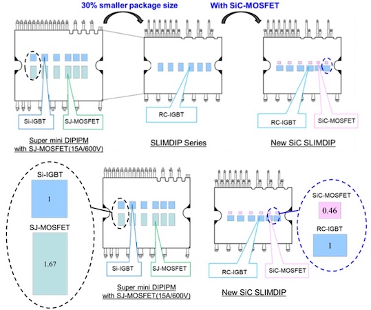
Figure 1. Package comparison of Super Mini DIPIPM with SJ-MOSFET, conventional SLIMDIP, and Hybrid SiC SLIMDIP. Image used courtesy of Bodo’s Power Systems [PDF]
New Gate Drive with Delay Control for Hybrid SiC SLIMDIP
When driving parallel-connected SiC MOSFET chips and RC-IGBT chips using conventional drive circuits, there are concerns about hard switching and current concentration on the SiC MOSFET, as the SiC MOSFET chips may turn on before the RC-IGBT chips. Therefore, a new state-of the-art drive IC was developed for Hybrid SiC SLIMDIP adapting sequential control of the gate drive signals by implementing a time delay between the gate drive pulses which are applied to each of the RC-IGBT chip and the SiC MOSFET chip (Figure 2).
The delay control avoids any hard switching operations of the SiC MOSFET chip during turn-on and turn-off states so that the switching losses of the SiC MOSFET chip is prevented, leading to soft switching. Hence, SiC MOSFET chip generates only DC loss and are allowed to be minimized down to the required size.
Static Characteristics of Hybrid SiC SLIMDIP
The Static characteristic of a power stage, impacting the DC losses, can be significantly enhanced by operating an RC-IGBT chip and a SiC MOSFET chip in parallel. As shown in Figure 3., Hybrid SiC SLIMDIP static characteristic in low current region below the built-in potential of the RC-IGBT is dominated by SiC MOSFET chip portion whereas in the current region above the built-in potential of the RCIGBT is dominated by combination of static characteristic of both the RC-IGBT chip and the SiC MOSFET chip.
Inverters for consumer and pump applications often operate at steady low-load operation for extended periods hence the new enhanced static characteristic across the entire current region of Hybrid SiC SLIMDIP can meet the market demand, providing higher efficiency particularly at steady low-load operation.
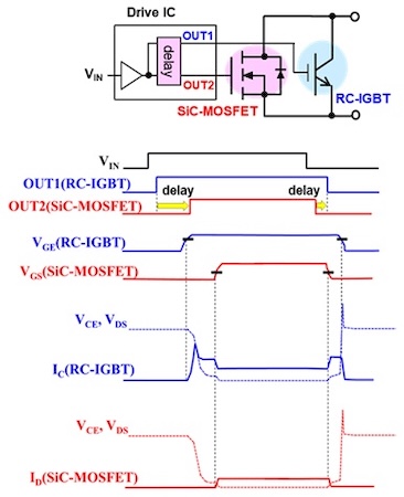
Figure 2. Developed drive circuit and timing chart. Image used courtesy of Bodo’s Power Systems [PDF]
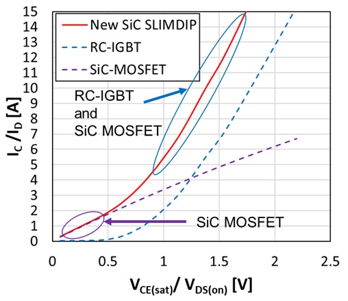
Figure 3. Static characteristics of Hybrid SiC SLIMDIP (Condition: VD=15 V, Tj =125°C). Image used courtesy of Bodo’s Power Systems [PDF]
Static Characteristics and Switching Characteristics of Full SiC SLIMDIP
Static Characteristics
In Figure 4a forward and in Figure 4b reverse conduction characteristics of 15A/600V Full SiC SLIMDIP and 15A/600V RC-IGBT utilized conventional SLIMDIP are shown. As can be seen, static characteristics of Full SiC SLIMDIP are improved over the entire current range compared with that of RC-IGBT utilized conventional SLIMDIP Series.
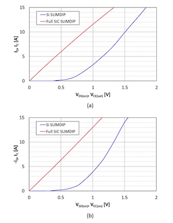
Figure 4. a) Forward static characteristic, b) Reverse static characteristic of Full SiC SLIMDIP and RC-IGBT SLIMDIP (Condition: VD=15 V, Tch/ Tj =125°C, Si SLIMDIP: SLIMDIP-L). Image used courtesy of Bodo’s Power Systems [PDF]
Full SiC SLIMDIP and RC-IGBT SLIMDIP turn-on and turn-off waveforms are shown in Figure 5a, Figure 5b, and Figure 5c respectively. As expected, Full SiC SLIMDIP has lower recovery and turn-on losses compared with that of RC-IGBT SLIMDIP. On the other hand, since SiC MOSFET has the minority carrier structure, no tail current occurs during turn-off so that turn-off losses could be improved as well. As illustrated in Figure 4c, improvement of switching characteristic of Full SiC SLIMDIP can be seen in the entire current region compared with that of RC-IGBT SLIMDIP.
Power Loss Comparison of SLIMDIP Series
Carrier Frequency vs. Allowable Output Current
Figure 6 shows the characteristics of the effective output current of Io vs. the carrier frequency under the condition that the average operating junction temperature Tj of the power chips remain below 125°C for safe operation whilst the heat sink temperature Tf is at 100°C.
The applications, where DIPIPM are used could vary widely, thus the applied carrier frequencies during operation could range from several kHz up to 20 kHz. As shown in Figure 6, Full SiC SLIMDIP, with overall reduced power losses, does not only allow larger out put current for the full range of carrier frequencies compared with that of SLIMDIP-L (Si SLIMDIP) but also allow larger output current at high carrier frequencies compared with that of SLIMDIP-X (Si SLIMDIP) (600V / 20A), having equipped with a higher rated current Si RC-IGBT.
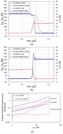
Figure 5. a) Turn-on switching waveforms, b) Turn-off switching waveforms, c) Switching Characteristics of Full SiC SLIMDIP and RC-IGBT SLIMDIP (Condition: VDD/VCC=300 V, VD=15 V, VIN=0↔5 V, Inductive Load, Tch/Tj =125°C, Si SLIMDIP: SLIMDIP-L). Image used courtesy of Bodo’s Power Systems [PDF]
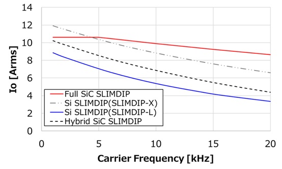
Figure 6. Effective Current vs. Carrier Frequency Characteristics (Conditions: Sinusoidal PWM, VDD/VCC=300 V, VD=15 V, M = 1, PF=0.8, Tch/Tj =125°C, Tf =100°C, Rth(cf)=0.3K/W(1/6 module), Rth(j-c)=Max value(1/6 module). Image used courtesy of Bodo’s Power Systems [PDF]
Hybrid SiC SLIMDIP
Figure 7 demonstrates the loss comparison between conventional RC-IGBT based SLIMDIP types, namely SLIMDIP-L and SLIMDIP-W, with Hybrid SiC SLIMDIP at steady low-load operation. Based on these results, utilization of Hybrid SiC SLIMDIP has reduced total losses by 47% and 40% compared with that of SLIMDIP-L and SLIMDIP-W respectively.
Since Hybrid SiC SLIMDIP shares DC losses between the RC-IGBT chip and the SiC MOSFET chip the losses generated within the RCIGBT chip as well as the junction temperature could be reduced compared with those of conventional SLIMDIP. Hence, Hybrid SiC SLIMDIP can increase the output current capability of an inverter stage further or have lower junction temperature levels at the same output current level compared with those of conventional SLIMDIP. As illustrated in Figure 8 the junction to case temperature difference (ΔTj-c) of Hybrid SiC SLIMDIP can be reduced by 34 % (approximately 8 K) at an inverter output current (IO) of 7.5 Arms.
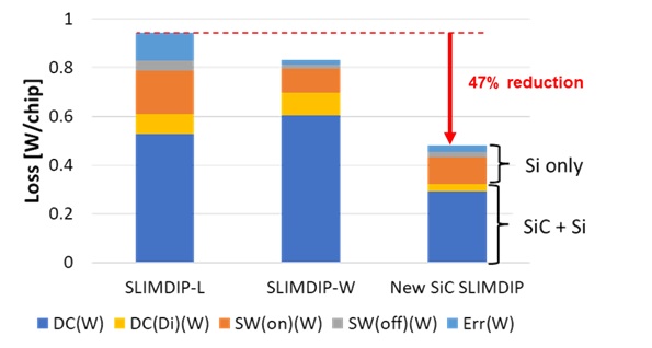
Figure 7. Loss simulation result comparison (Conditions: 2 phase modulation, VCC=300 V, IO=1.5 Arms, VD=15 V, fc=5 kHz, PF=0.8, M=1.1547). Image used courtesy of Bodo’s Power Systems [PDF]
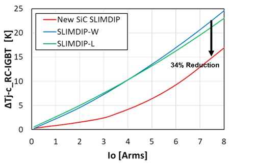
Figure 8. Junction temperature rise comparison between SLIMDIP-L, SLIMDIP-W and Hybrid SiC SLIMDIP (Conditions: 2 phase modulation, VCC=300 V, IO=7.5 Arms, VD=15 V, fc=5 kHz, PF=0.8, M=1.1547). Image used courtesy of Bodo’s Power Systems [PDF]
Full SiC SLIMDIP
Full SiC SLIMDIP has the efficiency advantage over both steady low-load and full load range. To illustrate this efficiency advantage and loss reduction, two distinct applications focusing on distinct operating conditions have been considered and related loss calculations have been.
The first application focused on is the air conditioner example where low output current and low switching frequency are the dominant operation characteristics for the entire operation life of the power module. As can be seen in Figure 9, Hybrid SiC SLIMDIP provides up to 40% of loss reduction whereas Full SiC SLIMDIP provides up to 82% of loss reduction compared with the overall losses of RC-IGBT SLIMDIP.
The second application focused on is the washing machine example in which high output current and high switching frequency are the dominant operation characteristics for the entire operation life of the power module. As can be seen in Figure 10, Hybrid SiC SLIMDIP provides up to 25% of loss reduction whereas Full SiC SLIMDIP provides up to 65% of loss reduction compared with the overall losses of RC-IGBT SLIMDIP.
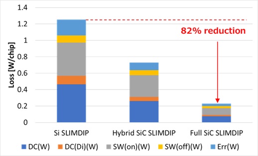
Figure 9. Loss Simulation Result for Air Conditioner (Conditions: Sinusoidal, VDD/VCC=300 V, IO=1.5 Arms, VD=15 V, fc=5 kHz, PF=0.8, M=1, Tch/Tj =125°C, Si SLIMDIP: SLIMDIP-L). Image used courtesy of Bodo’s Power Systems [PDF]
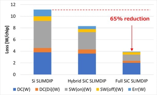
Figure 10. Loss Simulation Result for Washing Machine (Conditions: Sinusoidal, VDD/VCC=300 V, IO=7.5 Arms, VD=15 V, fc=15 kHz, PF=0.8, M=1, Tch/Tj =125°C, Si SLIMDIP: SLIMDIP-L). Image used courtesy of Bodo’s Power Systems [PDF]
Conclusion
SLIMDIP with 600V RC-IGBT technology has become a sought after DIPIPM for whitegoods and low power industrial drives applications. Mitsubishi Electric has developed Hybrid SiC SLIMDIP, especially for steady low-load efficiency, and Full SiC SLIMDIP, steady low-load and full load efficiency, to address increasing efficiency requirements in home appliances and industrial drive applications.
* DIPIPM and SLIMDIP are trademarks of MITSUBISHI ELECTRIC CORPORATION.
This article originally appeared in Bodo’s Power Systems [PDF] magazine and is co-authored by Keisuke Kawamoto and Dr. Mustafa Cem Ozkilic, Mitsubishi Electric Europe B.V., Germany and Akiko Goto, Mitsubishi Electric Corporation, Japan