Facebook
 Google
 GitHub
 Linkedin
Series RC Circuit Analysis
The behavior of a series RC circuit can be described using various electrical properties such as resistance, capacitance, and impedance, and understanding these properties is essential to analyzing and designing circuits in electrical engineering.
In a series RC circuit, the resistor and the capacitor are connected in a series configuration, meaning that the current flowing through the circuit passes through both components sequentially. The resistor resists the flow of current, while the capacitor stores energy in the form of an electric field.
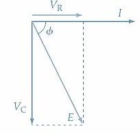
A series circuit consisting of capacitance (C) and resistance (R) is shown in Figure 1(a), and the waveforms and phasor diagram for the circuit are illustrated in Figures 1(b) and (c), respectively. The waveform of current (I) is drawn first because it is common to both series-connected components (R and C), as in Figure 1(b).
The voltage (VR) across the resistance is always in phase with the current through the resistance. Thus, the waveform of VR in Figure 1(b) is drawn in phase with the current waveform. The current through the capacitor leads the capacitor terminal voltage (VC) by 90°; consequently, the VC waveform is drawn 90° lagging the current wave. The applied voltage E is the resultant of the two-component voltages, VR and VC, and its waveform can be obtained simply by summing the instantaneous levels of VR and VC, and it is seen that E lags I by an angle ɸ, which is less than 90°.
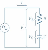
(a) Series RC circuit
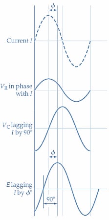
(b) Circuit waveforms
(c) Phasor diagram
Figure 1. In a series-connected RC circuit, the current leads the capacitor voltage (VC) by 90° and leads the supply voltage (E) by an angle less than 90°. Image used courtesy of Amna Ahmad
Phasor Diagram
The phasor diagram for the series RC circuit is drawn by starting with the current phasor again because the current is the common quantity in a series circuit. A horizontal line is drawn to scale representing current (I) [ Figure 1(c)]. Because the resistor voltage is in phase with I, VR is represented by another horizontal line drawn alongside I. The capacitor voltage lags I by 90°, so the VC phasor is drawn vertically at an angle of -90° for I. The resultant of the phasor addition of VC and VR represents the applied voltage (E). Once again, it is seen that E lags I by an angle ɸ, which is less than the 90°angle that would exist between E and I in a pure capacitive circuit.
Circuit Equations
From Figure 1(c), the rectangular form expression for E in the series RC circuit is
\[E=V_{R}-jV_{C}\,(1)\]
Or in polar form
\[E=\sqrt{V^{2}_{R}+V^{2}_{C}}\angle tan-1{\Big(}\frac{V_{C}}{V_{R}}{\Big)}\,(2)\]
Divide Equation 1 by I
\[\frac{E}{I}=\frac{V_{R}}{I}-j\frac{V_{C}}{I}\]
The quantity VR/I is the voltage across the resistance divided by the current through the resistance. So, VR/I can be replaced with R. Also, VC/I is the capacitor voltage divided by the current through the capacitor, which can be replaced with the capacitive reactance XC. The quantity E/I is neither resistance nor capacitive reactance because it has both as component parts. In this case, E/I is termed impedance and is given the symbol Z. Therefore, as illustrated in Figure 2, the above equation can be restated.
\[Z=R-jX_{C}\,(3)\]
In Equation 3, R is resistance in ohms, XC is capacitive reactance in ohms, and Z is impedance in ohms. Also,
\[|Z|=\sqrt{R^{2}+X^{2}_{C}}\,(4)\]
And
\[\Phi=tan-1{\Big(}\frac{-X_{C}}{R}{\Big)}\,(5)\]
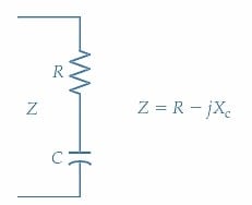
Figure 2. The impedance of a circuit consisting of a resistor and capacitor connected in series is (Z = R - XC). Image used courtesy of Amna Ahmad
Combining Equations 4 and 5
\[Z=\sqrt{R^{2}+X^{2}_{C}}\angle tan-1{\Big(}-\frac{X_{C}}{R}{\Big)}\,(6)\]
Equation 6 represents the conversion from rectangular form (Z=R +jX) to polar form (Z∠ϕ).
Impedance Diagram
As explained for the series RL circuit, the quantities Z, R, and XC are not phasor quantities because they have fixed values. To distinguish the vector diagram of impedance, reactance, and resistance from a phasor diagram, it is usually drawn in triangular form and is referred to as an impedance diagram. The impedance diagram for a series RC circuit is shown in Figure 3. A horizontal line is first drawn to scale to represent R, then the -j component (XC) is drawn at -90° with respect to R. Z is the hypotenuse of the impedance triangle, and the phase angle of Z with respect to R is ɸ.
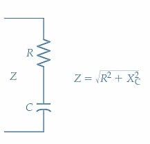
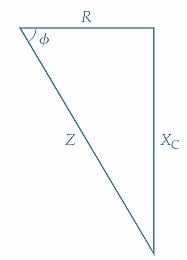
Figure 3. Impedance diagram (or impedance triangle) for a series-connected RC circuit. Capacitive reactance vector XC is drawn (down) from the resistance vector at a -90°angle. The impedance vector Z is the resultant of R and XC. Image used courtesy of Amna Ahmad
Admittance
As in the case of conductance (the reciprocal of resistance) and susceptance (the reciprocal of reactance), the reciprocal of impedance is an important quantity that can be usefully applied in circuit analysis. The admittance (symbol Y) is the reciprocal of impedance (Z), and its unit is Siemens (S).
Admittance:
\[Y=\frac{1}{Z}\,(7)\]
When Z is expressed in ohms in Equation 7, Y is in Siemens.
Analysis Procedure for Series RC Circuit
Follow these steps when analyzing series RC circuits.
1. Calculate the capacitive reactance \(X_{C}=\frac{1}{2\pi fC}\)
2. If there is more than one resistive component, calculate the total resistance
\[R=R_{1}+R_{2}+...\]
3. Calculate the impedance
\[|Z|=\sqrt{R^{2}+X^{2}_{C}}\]
4. Calculate the phase angle \(\Phi = tan-1{\Big(}\frac{X_{C}}{R}{\Big)}\)
5. Calculate the current \(I=\frac{E}{Z}\)
6. Determine the resistive voltage \(V_{R}=IR\,or\,V_{R}=E\,cos\,cos\Phi\)
7. Determine the capacitive voltage \(V_{C}=IX_{C}\,or\,V_{C}=E\,sin\,sin\,\Phi\)
Example 1
Analyze the series RC circuit in Figure 4 to determine the current, the voltage across R, the voltage across C, and the phase angle of the current with respect to the supply voltage.
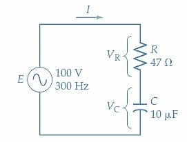
Figure 4. Series connected RC circuit for Example 1. Image used courtesy of Amna Ahmad
Solution
Capacitive reactance:
\[X_{C}=\frac{1}{2\pi fC}=\frac{1}{2\pi\times300Hz\times10\mu F}\approx53.1\Omega\]
Circuit Impedance:
Equation 4
\[|Z|=\sqrt{R^{2}+X^{2}_{C}}=\sqrt{(47\Omega)^{2}+(53.1\Omega)^{2}}=70.9\Omega\]
Phase angle:
Equation 5
\[\Phi=tan-1{\Big(}\frac{-X_{C}}{R}{\Big)}=tan-1{\Big(}\frac{-53.1\Omega}{47\Omega}{\Big)}\approx-48.5\degree\]
Circuit current:
\[I=\frac{E}{Z}=\frac{100V}{70.9\Omega\angle-48.5\degree}\approx1.41A\angle48.5\degree\]
Referring to the series RC circuit phasor diagram Figure 1(c):
Resistor voltage:
\[V_{R}=E\,cos\,cos\,\Phi=100V\,cos\,cos{\Big(}-48.5\degree{\Big)}\approx66.3V(=I\times R)\]
Capacitor voltage:
\[V_{C}=E\,sin\,sin\,\Phi=100V\,sin\,sin{\Big(}-48.5\degree{\Big)}\approx-74.7V{\Big(}=I\times X_{C}{\Big)}\]
Example 2
Draw the phasor diagram for the series RC circuit analyzed in Example 1.
Solution
The phasor for the current (I) is first drawn horizontally (see Figure 5).
VR is drawn in phase with the current.
VC is drawn lagging the current by 90°.
E lags the current by ɸ and is also the result of VC and VR.
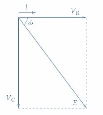
Figure 5. Phasor diagram for the series RC circuit in Example 2. Image used courtesy of Amna Ahmad
Takeaways of Series RC Circuit Analysis
A series RC circuit is an important electrical circuit that comprises a resistor and a capacitor connected in series with a power source. The behavior of a series RC circuit can be analyzed using impedance and phasor diagrams, which provide a graphical representation of the complex impedance and phase relationship between the voltage and current. The impedance diagram represents the impedance of the circuit as a vector in a complex plane, while the phasor diagram represents the phase relationship between the voltage and current as a rotating vector. Understanding these diagrams is crucial for analyzing and designing series RC circuits and comprehending the behavior of capacitive elements in electrical circuits.
Featured image used courtesy of Adobe Stock