Facebook
 Google
 GitHub
 Linkedin
Total Cost of Ownership in SiC Motor Drives—the Big Picture
This article examines the technical benefits and total cost of ownership of SiC in two types of motor drive applications.
This article is published by EEPower as part of an exclusive digital content partnership with Bodo’s Power Systems.
After commercial success in a variety of applications, silicon carbide is ready to be deployed in the cost-competitive industrial motor drive market. The practical benefits of SiC power modules aren’t just limited to efficiency gains. An examination of two motor drive types shows savings across the board. The key is to look at the big picture.
Silicon carbide MOSFETs have proven to be a commercially viable alternative to silicon IGBTs in solar, energy storage systems, electric vehicles, and EV chargers. These are all applications where efficiency gains and filter size reductions offset any increased semiconductor material cost. Industrial motor drives, being a commodity, have required low-cost, robust power semiconductors with less regard to device-level efficiency. Now, rising global energy costs and regulatory requirements concerning current harmonics and CO2 emissions are pushing designers to look for higher-efficiency solutions. This, coupled with the availability of mass-produced, short-circuit-capable SiC power devices, means SiC has a place in motor drives. By looking at two different drive types, the technical benefits of SiC in different circuit positions can be examined.
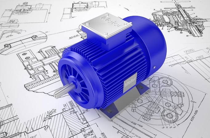
Image used courtesy of Adobe Stock
Line Side (Low Harmonic/Regenerative Drive)
Modern performance drives often incorporate an active front end (AFE) utilizing active devices instead of passive rectifiers for the line connection for two reasons. 1.) to address the harmonic content the drive imparts on the grid. A 3-phase bridge of active devices can synchronize with the line frequency and draw sinusoidal currents from the line close to the unity power factor. This topology supports meeting harmonics requirements (e.g., IEEE 519 in the USA) and improves power grid utilization. This topic is gaining importance, driven by the ongoing electrification of industries and applications. 2.) the ability to push energy back to the grid. This is beneficial in applications that can generate energy during operation, which otherwise must be dissipated using a passive brake resistor. These could be servo drives, cranes, elevators, escalators, downhill conveyors, dynamometers, etc.
The simplest AFEs typically use circuits, as illustrated in Figure 1. For such, replacing IGBTs and their associated freewheeling diodes with SiC MOSFETs can give multiple benefits for the whole system.
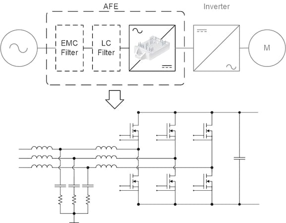
Figure 1. Typical active front-end topology. Image used courtesy of Bodo’s Power Systems [PDF]
A complete 20 kW (27HP) AFE drive with the following operating parameters is examined:
- VDC: 750 V
- Vline: 400 V
- Iline: 30 A
- PF: 0.98
- fline: 50 Hz
- fsw: Si = 5 kHz, SiC = 20 kHz
- Rth(s-a): 0.31 K/W
- Tamb: 40°C
The baseline Si IGBT power module for this comparison uses the latest generation (7th) 1200 V/50 A IGBT, whereas the selected SiC MOSFET power module uses a 1200 V/18 mΩ MOSFET. Both modules utilize the same package, a SEMITOP E1 from Semikron Danfoss. In this simulation, the switching frequency of the SiC is increased until the same junction temperature as the Si device is reached.
Table 1. Simulated AFE application comparison
|
Module |
Si IGBT SK50GD12T7ETE1 |
SiC MOSFET SK50MD120RM04ETE1 |
|
|
Switching Frequency |
5 kHz |
20 kHz |
(4x) |
|
AFE Losses |
Filter: 463 W Converter: 247 W 710 W |
Filter: 291 W Converter: 175 W 466 W |
(-34%) |
|
LCL Filter Volume |
8225 cm3 |
2448 cm3 |
(-70%) |
|
LCL Filter Weight |
19.4 kg |
10.2 kg |
(-47%) |
Even at four times the carrier frequency, the SiC devices exhibit 34% lower total losses per 3-phase circuit. Additionally, there is a direct impact on the sizing of LCL filter. The higher switching frequency yields a reduction in the required inductance and capacitance. The total weight of the inductors is nearly halved, while the overall volume is reduced by 70%. While the cost of SiC power modules is higher than Si devices, the total cost of ownership for the system must be considered:
• Smaller drive volume and weight:
• Reduced shipping, packaging, and storage space
• Easier installation
• Smaller panels and installation space
• Reduced watt losses
• Energy savings and cost reduction
• Lower cooling requirements
When examined in a wider scope, the substantial benefits enabled by SiC not only compensate for the cost of components. In AFE applications they also provide substantial cost benefits over the product life.
Inverter Side (Conventional Drive)
The inverter side of a drive, connected to the motor, presents challenges to implementing SiC. Here, in contrast to the AFE example, a few limitations and key requirements must be considered:
- The inverter must be able to withstand short circuits
- dv/dt must be limited (e.g. <5 kV/µs) to avoid damage to the motor
- Switching frequency is limited to keep drive losses at an acceptable level and to avoid excessive leakage current in shielded motor cables
Short circuit capability of SiC MOSFETs has long been a critical topic. However, with the latest generations, SiC devices are now available that can handle short circuits for a few microseconds, making them a viable option for motor drives.
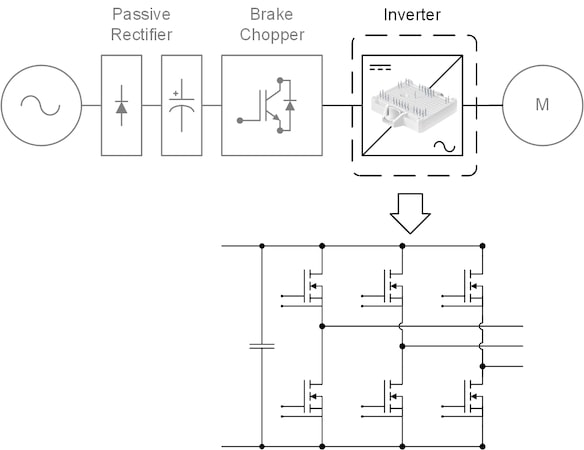
Figure 2. Motor drive with passive rectifier. Image used courtesy of Bodo’s Power Systems [PDF]
As can be seen from the schematic in Figure 2, there are no magnetic components that could be reduced by increasing the switching frequency. Nevertheless, in this application, SiC can still provide valuable benefits. This is illustrated by an exemplary 15kW (20HP) motor drive with the following parameters, as often found in variable torque applications:
- VDC: 560 V
- Vout: 355 V
- Iout: 26 A
- Overload: 110%/1 min
- PF: 0.98 (permanent magnet motor)
- fout: 50 Hz
- fsw: Si/SiC = 5 kHz (dv/dt limited to 5 kV/µs)
- Rth(s-a): 0.31 K/W
- Tamb: 50°C
The baseline Si IGBT power module for this comparison uses the latest generation (7th) 1200 V/35 A IGBT in the SEMITOP E2 package. The selected SiC MOSFET power module uses a 1200 V/18 mΩ MOSFET. This MOSFET is the latest 4th generation from ROHM Semiconductor with a rated 2 µs short circuit capability (VG = 18 V, Tj = 150°C, VDC = 720 V) when used in Semikron Danfoss power modules. For both example modules, the external gate resistors have been selected to limit the dv/dt to 5 kV/µs.
The application is driving a centrifugal pump with quadratic torque characteristics, as shown in Figure 3. Real-world pumps operate mainly in the 40 to 80% speed range. This operating area corresponds to a current range where the SiC MOSFET has lower conduction losses than the Si IGBT. As the MOSFET is slowed down to 5kV/µs there is little advantage in switching losses compared to the IGBT solution. However, due to the linear forward characteristics, the MOSFET exhibits much lower conduction losses.
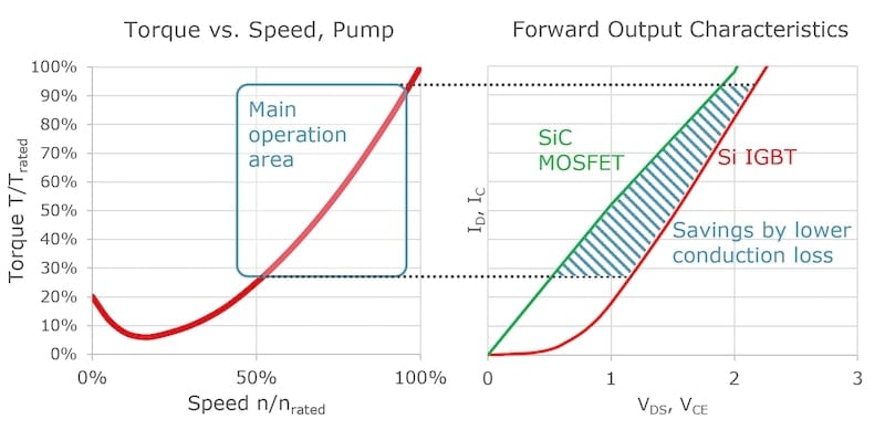
Figure 3. Centrifugal pump torque vs. speed characteristic. Image used courtesy of Bodo’s Power Systems [PDF]
The losses and efficiency for an entire 15 kW drive (including diode front end, DC link capacitors, and inverter) are shown in Figure 4 for a Si IGBT (grey) and SiC MOSFET (red).
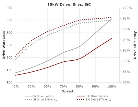
Figure 4. 15 kW drive losses and efficiency. Image used courtesy of Bodo’s Power Systems [PDF]
The results show a clear advantage in losses for SiC across the applicable speed range. Losses in the SiC-equipped drive are 7% less than the Si version at low speed and 22% less at full speed. This equates to a 0.6% increase in total efficiency at low speed and a 0.5% increase at high speed. These values can be equated to real-world savings by looking at the time spent at different operating speeds for a drive during operation. The annual load estimate in Figure 5 is based on the typical application of an industrial pump drive. If the losses at each load point are calculated, the total energy lost over one year can be calculated for each drive.
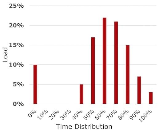
Figure 5. Pump drive, annual average load distribution. Image used courtesy of Bodo’s Power Systems [PDF]
Over one year, the SiC-equipped drive has only 377kWh of accumulated energy expenditure versus the Si-equipped drive with 651 kWh. This 42% reduction in energy has real environmental and financial implications. Greenhouse gases are reduced by 125 kg-CO2 annually (global mix, 2023). The increased cost of the SiC-equipped drive is compensated after one year in a country like Germany (0.20 €/kWh, 2023), or in less than three years in a country like the United States, which has significantly lower electricity costs.
Finally, there are physical advantages to utilizing SiC, as a drive of a certain power rating can be made smaller using SiC. Further simulations have shown the lower semiconductor power losses with SiC allow a reduction of heatsink volume up to 71% for the same temperature rise. For industrial drives, this means that the airflow and number of cooling fans can be reduced. Additionally, the panel and cabinet the drive is installed in can be smaller and lighter, reducing material, logistic, and installation costs. Conversely, if the same thermal design is maintained, the output power for a given motor drive frame size can be increased by up to 25%.
SiC Power Modules
To address the needs of drive manufacturers, Semikron Danfoss offers SiC power modules in common topologies and packages (Figure 6). The SEMITOP E, MiniSKiiP, and SEMITRANS Classic are all available with the latest Gen. 4 SiC MOSFET from ROHM, featuring short-circuit capability and unipolar gate control. These devices are pin-compatible existing Si devices and are available with high-performance pre-applied thermal interface materials. For the highest power cycling reliability, sintered chips are available in the MiniSKiiP package. These enable the use of SiC in applications with severe overload peaks like servo or robotic drives.
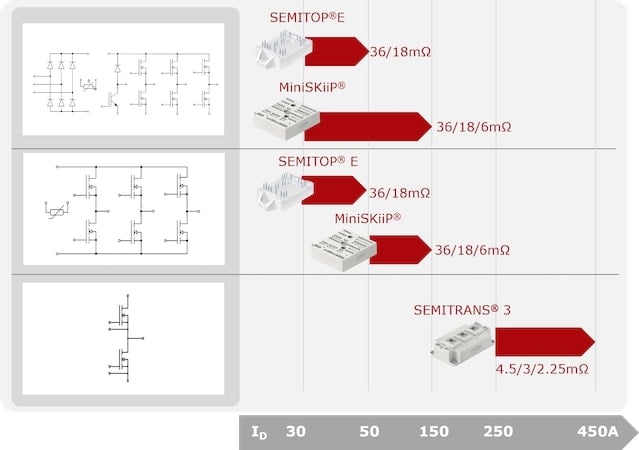
Figure 6. SiC-equipped power modules. Image used courtesy of Bodo’s Power Systems [PDF]
The Big Picture
Both examples offer a taste of the new degrees of freedom that drive manufacturers and benefit end users when switching to SiC, even without pushing the material to its limit. For specialty drive applications such as high-speed motors in turbo compressors, even further benefits can be obtained. These cases are often not limited by the dv/dt and switching frequency restrictions mentioned here.
A cost comparison is meaningless when done at the module level. The view must be widened to include the drive system and total cost of ownership. In this case, SiC brings overall benefits that outweigh the higher module cost. With high performance and new robustness, SiC is the choice for the next generation of industrial motor drives.
This article originally appeared in Bodo’s Power Systems [PDF] magazine.