Facebook
 Google
 GitHub
 Linkedin
Solving Military-Avionics DC-DC Power Challenges with Modularity—Part 4
While the first three parts in this article series detailed military and avionic standards and front-end solutions, this last Part 4 delves into the core of energy conversion.
This article is published by EEPower as part of an exclusive digital content partnership with Bodo’s Power Systems.
Designing a full DC/DC converter with discrete components is definitely the most complex, time-consuming, and risky approach. Consequently, engineers who choose this path probably have compelling reasons. Sometimes the required specifications aren’t available in Commercial Off-The-Shelf (COTS) products.
Other times, the form factor of a COTS DC/DC converter – despite offering better power density – doesn’t fit the customer’s needs, or the designer requires a unique function unavailable in COTS solutions. For engineers opting for a discrete design, believing it will outperform a COTS-based solution or hoping to master component procurement, it is paramount to carefully balance the risks and benefits.
The multi-phase design process itself presents significant challenges in terms of topology choice, magnetics & switching component selection, as well as control loop and protections.
Topology Choice
The choice of topology is a critical decision that requires a highly skilled power supply designer. For example, selecting a flyback topology for a low-power isolated DC/DC converter leverages its low component count, which improves reliability through higher MTBF figures. To simplify design, engineers may choose Continuous Conduction Mode (CCM) operation.
However, CCM demands a larger transformer with a correctly rated air gap to prevent core saturation, and an accurate output voltage control for limiting the light loads' voltage rise. Conversely, Discontinuous Conduction Mode (DCM) yields a smaller transformer size and more stable light-load voltage regulation—at the expense of higher ripple current that increases components stress, lowering the MTBF.
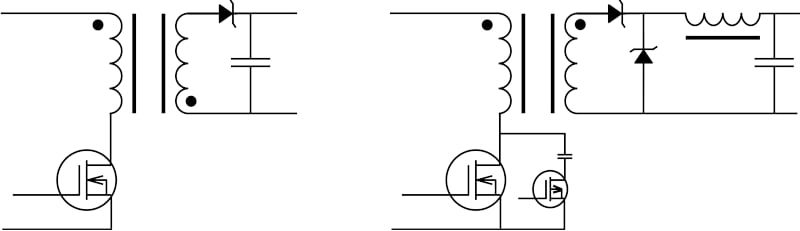
Figure 1. The flyback topology, with its low component count and a single magnetic circuit that provides both isolation and energy storage, is ideal for achieving high MTBF. The forward topology using a transformer for isolation and a separate power inductor for energy storage is essential for high powers. Image used courtesy of Bodo’s Power Systems [PDF]
Magnetics and Switching Component Selection
Success demands expert knowledge of state-of-the-art market offerings. The limited availability of branded off-the-shelf transformers often forces engineers to adapt designs to magnetic specifications, compromising circuit flexibility and performance. Opting for custom transformers entails extended design cycles, including iterative development and qualification phases.
ACR (resistance in alternative current mode) and DCR (resistance in direct current mode), key contributors to transformer efficiency, cannot be taken as simple figures from off-the-shelf transformer datasheets. Instead, they require accurate evaluation through complex computations prior to design, followed by verification on initial prototypes.
Control Loop and Protection
Following the core power stage definition, a comprehensive design of low-power support electronics is essential. This encompasses the regulation control loop, critical safety/protection functions (UnderVoltage Lockout - UVLO, Over-Current Protection – OCP, Over-Voltage Protection – OVP), and auxiliary features such as switching frequency synchronization, remote control, and monitoring.
Design considerations extend beyond functionality. In this context, it is important to consider reliability considerations as well as component obsolescence & sourcing.
Reliability Considerations
Although opto-coupler-based analog feedback loops are simple, their inherent reliability issues make them unsuitable for demanding military and avionics applications. A more robust solution uses a discrete magnetic feedback circuit, which transmits error signals through a low-power transformer. This design offers high MTBF and superior dependability, despite its greater complexity.
Component Obsolescence and Sourcing
Proactively managing component availability and obsolescence demands significant resources. Ensuring manufacturability over extended lifecycles (10-30 years) requires implementing multisourcing strategies and monitoring component change notifications during the initial design phase. As electronic specialists, most design engineers underestimate the technical and financial constraints associated with preventing obsolescence.
COTS Converter
With a comprehensive range of DC/DC board converters covering power needs from 4 W to 1000 W, Gaia Converter has spent the last three decades working on power conversion technologies. Today, the company offers several Hi-Rel COTS board-mounted DC/ DC converters.
Its low-power DC/DC converters (6–80 W) combine CCM and DCM operation to extend input voltage range boundaries without efficiency compromise, while quarter-brick and half-brick converters (155–500 W) leverage a copper IMS (isolated metallic substrate) base construction to avoid power derating at high temperatures.
Gaia Converter’s proprietary magnetic feedback technology, introduced years ago, extends the lifecycle of these high-power-density converters by eliminating drift risks inherent in opto-coupler feedback control loops.
|
COTS REF. |
MGDM04 |
MGDD8 |
MGDM75 |
MGDM155 |
MGDM500 |
MGDM500 |
|
Parameters |
|
|||||
|
output power |
4 /10/18 |
6/8/20/40/80 |
75 /100 |
100/250 |
500 |
500 to 3000 |
|
Output number |
Up to 3 |
2 |
1 |
1 |
1 |
1 |
|
Wide input |
4:1 |
9:1 to 12:1 |
5:1-10:1 |
5:1 |
5:1 |
5:1 |
|
Output voltage |
3.3 to 24 |
3.3 to 54 |
3.3 to 28 |
3.3 to 28 |
12 to 48 |
12 to 48 |
|
synchronization |
No |
Yes |
Yes |
Yes |
Yes |
yes |
|
MTBF (Hours) |
1650 000 |
1025000 |
600000 |
490000 |
1724000 |
1724000 |
|
package |
DIL |
1/8 Brick to 2"x1.6"x0.5" |
¼ Brick |
¼ Brick |
½ Brick |
½ Brick |
Table 1. The modular approach allows flexibility with available power from 4W to 500W +, and input range from 4:1 to 12:1.
Power Architecture
Considering all mandatory functions for building a Mil-Aero compliant power supply, a COTS-based modular approach appears remarkably straightforward. Leveraging COTS solutions provides designers with simplified development processes and accelerated qualification timelines. The power designer’s responsibility reduces to implementing the module arrangement detailed in Gaia Converter’s application notes [4.1], adapting them to specific requirements
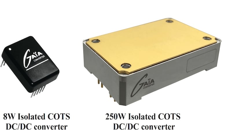
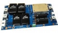
Figure 2. The 8 Watts 1/16th brick and 250 Watts 1/4 brick COTS isolated DC/DC converters are compact board-mounted modules. Image used courtesy of Bodo’s Power Systems [PDF]
PCB Considerations
However, project success depends on the engineer’s ability to design a state-of-the-art PCB for module interconnections. While COTS modules greatly simplify design, the PCB layout demands specialized skills to avoid compromising performance despite module quality. Fundamentally, when routing copper traces, designers must address at least five key questions:
1. How resistive will my copper trace be? (and consequently, what will its temperature be during operation).
2. How inductive will the copper trace be?
3. Will radiated energy quickly find a return path?
4. Will the routed trace favor undesired signal coupling between points?
5. Will creepage and isolation distances comply with requirements?
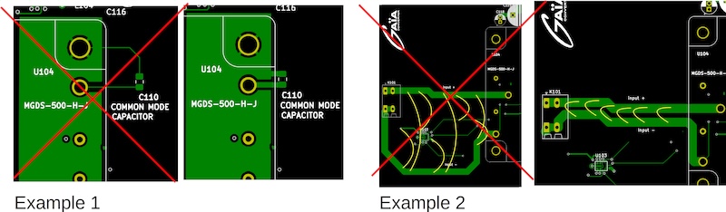
Figure 3. Traces that are too thin are inductive and cancel out the c110 effect (Example 1). Radiated field lines (in yellow) must be contained to avoid polluting secondary circuits in Example 2. Image used courtesy of Bodo’s Power Systems [PDF]
The answer to Question 1 lies in selecting the correct compromise between trace width and copper thickness. Answers to Questions 2 and 3 are addressed in Figure 3, where example 1 shows how an inductive thin trace can transform a low-impedance common-mode capacitor into a resonant LC circuit, while example 2 highlights the benefit of keeping a positive power track and its return path as close as possible to minimize radiated noise (radiated field lines shown in yellow). These simplified examples of good and bad practices use single-layer routing for clarity.
Utilizing multilayer PCBs and smart copper plane use are key elements that help the power supply PCB designer follow these best practices and ensure project success. Gaia-converter supports engineers in their PCB designs and offers fully documented demo board examples. Figure 4 illustrates a 500 W power supply compliant with Mil-Aero standards – an exceptionally simple architecture built around four proven high-reliability modules and described in Gaia-converter GTJ2050 service manual [4.2].
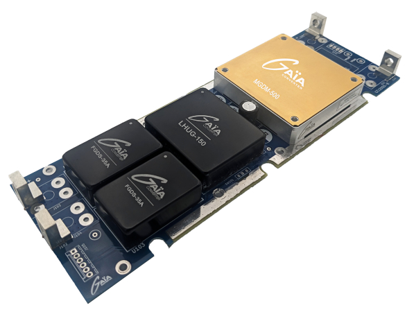
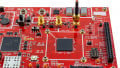
Figure 4. Based on four proven high-reliability modules, this design proposes a 500 W power supply that complies with Mil-STD 1275, Mil-STD-704, and Mil-STD-461. Image used courtesy of Bodo’s Power Systems [PDF]
For lower-power solutions, further simplification is achievable. The fully integrated FLHG-60-MN front-end module incorporates EMC filtering, voltage limiting, reverse polarity protection, and hold-up functionality. As this single module ensures full compliance, only two components are required to construct a high-reliability MilAero power supply. This 2”×3” solution exemplifies SWaP optimization. Extending this integration trend, Gaia Converter recently released the board-mountable PSDG48 module – consolidating all architectural functions within a single package.
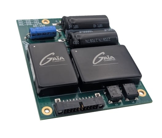
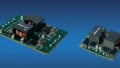
Figure 5. The 3.5”x3.30’’ 40 W power supply complies with Mil-STD461, Mil-STD-704, and DO-160 with a hold-up function thanks to the FLHG-60-MN integrated front end. Image used courtesy of Bodo’s Power Systems [PDF]
Conclusion
Engineers developing electronics for military or avionic applications often face demands for more complex digital, radio communication, and automated systems, resulting in soaring power consumption. However, as specialists in their domain, they may lack a full understanding of military and avionics standards, leading them to underestimate the challenges of developing compatible power supplies.
For engineers without Mil-Aero power expertise, attempting to design a discrete-component power supply can be misleading and ultimately undermine the entire project: the design might pass demanding standards like DO-254 and DO-178, but fail MIL-STD-461 or DO160 compliance due to power supply issues. Designing mil-aero power supplies can quickly become a titanic undertaking for non-specialists. For over 30 years, Gaïa Converter has offered qualified, hi-rel, board-mounted power modules that greatly simplify mil-aero designs.
References:
[4.1] https://www.gaia-converter.com/technical-support/evaluation-boards/
[4.2] https://www.gaia-converter.com/wp-content/uploads/2025/08/GTJ2050-C_service_manuel_Rev-B.pdf
[4.3] https://www.gaia-converter.com/products/lgds-600/
[4.4] https://www.gaia-converter.com/products/mgdm-500/
This article originally appeared in Bodo’s Power Systems [PDF] magazine.