Facebook
 Google
 GitHub
 Linkedin
Distribution Transformers and Voltage Regulation—Part 4: On- and Off-Load Tap Changers
In this article, we detail distribution transformer tap changers: fixed off-load (DETC) vs. dynamic on-load (OLTC) types, their operational roles, and coordination challenges in modern grids with DER.
Maintaining service voltage within ANSI C84.1 limits on modern feeders depends heavily on how distribution transformers adjust their turns ratio. Tap-changing hardware provides that adjustment, either by setting taps with the transformer out of service or by changing taps while energized.
Selecting the right tap-changing method and coordinating controls with other line devices have become more complex as distributed energy resources (DER) alter power flow and reactive power on feeders. Standards from IEEE and IEC define the hardware and performance limits, while manufacturer controls implement operating modes such as fixed setpoint and line drop compensation (LDC).
Off‑Load Tap Changers (NLTC/DETC)
De‑energized or “off‑circuit” tap changers (often noted on nameplates as DETC, OCTC, or NLTC) require the transformer to be out of service before a different tap can be selected. The device is a mechanical selector or switch connected to a series of fixed taps on one winding—commonly on the high‑voltage side—so that the turns ratio can be adjusted several percent above or below nominal. These devices are covered alongside on‑load units in IEEE C57.131, which distinguishes the permitted operating conditions and test requirements for each type.
Typical DETC ranges offered on distribution and substation transformers include ±2.5% and ±5% relative to nominal voltage. IEEE C57.12.10 states that, when specified, four high‑voltage taps for de‑energized operation shall be provided at +2.5%, +5%, −2.5%, and −5% of rated voltage, a pattern that remains prevalent in utility specifications. These fixed steps allow correction for anticipated feeder voltage conditions without introducing moving arcing contacts into the oil circuit.
Common applications for DETC settings include seasonal voltage correction and initial commissioning. In long rural feeders where summer peak loads drop primary voltage several percent, a DETC may be set at +2.5% (or +5% where justified) before the season, then returned toward nominal in moderate-load periods.
Likewise, during commissioning, a DETC can adjust the secondary to nameplate voltage under expected loading, avoiding unnecessary mid‑feeder regulators if margins are adequate. The approach is simple, but it is not dynamic; any midseason changes require an outage and switching work, which is one reason on‑load capability is attractive for substations feeding highly variable loads or DER.
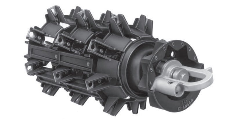
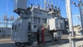
Figure 1. Off-load tap changer in a transformer. Image used courtesy of Eaton.
On‑Load Tap Changers (OLTC)
An on‑load tap changer (OLTC) changes taps while the transformer remains energized and carrying load, using a diverter mechanism that transfers current between adjacent taps without interruption. IEEE C57.131 defines performance and test methods for resistor-type and reactor-type OLTCs and their motor-drive mechanisms, and serves as the primary North American reference alongside IEC 60214-1.
Two control modes dominate OLTC service:
- Voltage setpoint control: the automatic voltage regulator holds a measured bus near a target (for example, 1.00 per unit on a 120‑V base) within a bandwidth, with an intentional time delay to avoid cycling on transients.
- Line Drop Compensation (LDC): the control intentionally biases the local measured voltage by an amount proportional to estimated line drop, using programmed R and X settings and the measured load current to maintain a remote “load center” voltage near the target. Manufacturer manuals describe how the control computes a compensated voltage from the R and X values (in volts on a 120‑V base) and real/reactive current components, and how forward/reverse settings are applied when power reverses.
Tap step size and range vary by equipment class. Step‑voltage regulators used on feeders provide ±10% regulation in 32 steps of approximately 0.625% each; IEEE C57.15 and IEC 60076‑21 describe these devices, and manufacturer instructions document the 32‑step, ±10% behavior. Substation power transformers with OLTCs frequently provide a ±10% range with about 16 steps (roughly 1.25% per step), a configuration often seen in utility and industrial specifications.
Mechanical OLTCs use diverter switches and selector contacts immersed in insulating liquid. Within this category, resistor‑type and reactor‑type switching topologies are common; both are addressed in IEEE C57.131. In recent years, hybrid or power‑electronic‑assisted OLTC concepts have been studied to reduce contact wear and arcing energy—typically inserting thyristors to carry current during commutation while mechanical contacts reposition. Fully electronic variants have appeared in research settings, though conventional mechanical OLTCs remain dominant in utility service.
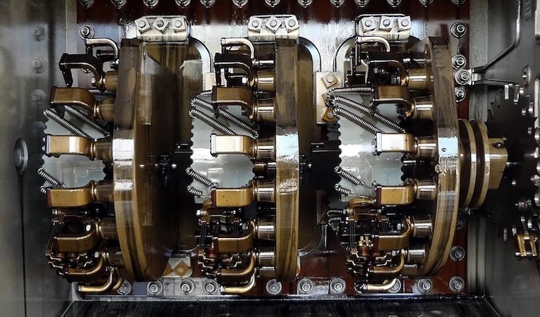
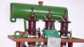
Figure 2. On-load tap changer in a transformer. Image used courtesy of Azo Materials.
Control Challenges
Interaction with Feeder Voltage Regulators
Many systems deploy a substation transformer OLTC at the feeder head plus one or more step‑voltage regulators (SVRs) downstream. Without coordination, setpoint bands can overlap, or LDC settings can target the same remote point from two ends, causing needless operations or unstable behavior. Guidance for parallels and device coordination appears in IEEE C57.153, which discusses LDC concepts and the need to consider distributed load effects in settings. Manufacturer manuals also detail forward/reverse modes to handle DER backfeed so that LDC biasing switches appropriately when power direction changes.
When power can reverse through a regulator—such as with significant PV downstream—the control must either operate in a bi‑directional LDC mode or revert to setpoint control with reverse‑power blocking, depending on utility practice. Controls that retain forward LDC bias during reverse flow can boost at the wrong time, worsening voltage excursions; modern firmware offers reverse LDC parameter sets and configurable thresholds to mitigate this.
Tap Hunting and Coordination Issues
Tap hunting—repeated raise/lower operations in short succession—arises when deadband and time delay are too small for the local voltage variability or when multiple devices react to the same disturbance. Classical analyses show that OLTC deadband width and dwell time influence the occurrence of limit cycles; poorly tuned combinations can produce persistent cycling even under quasi‑steady load dynamics. Practical OLTC controllers introduce a deadband of several volts (on a 120‑V base) and a time delay of tens of seconds to minutes to avoid acting on flicker, with additional dwell logic in advanced schemes.
Coordination becomes more delicate when SVRs, capacitors, and smart inverters are in the loop. Model‑predictive or heuristic supervisory controls embed OLTC discrete behavior (deadbands, delays, step limits) to prevent oscillations as reactive devices respond faster than mechanical tap changers. Field experience indicates that explicitly modeling OLTC nonlinearity improves stability and reduces operations.
Impact of DER on OLTC operation
DER changes feeder voltage profiles and power‑flow direction throughout the day. IEEE 1547‑2018 requires DER to include voltage regulation capabilities, such as volt‑VAR and volt‑watt functions, with defined performance categories and default settings; how those functions are activated is at the utility operator’s discretion. Properly tuned smart‑inverter controls can reduce extreme voltages and lessen OLTC operations compared with unity‑power‑factor DER, but poor coordination may increase tap movements or create control conflicts.
Field studies have documented increases in tap operations with growing PV penetration, particularly under variable cloud cover. Data from real feeders and controlled studies show that total operations can rise substantially as PV output ramps and reverses feeder power flow, driving the OLTC and SVRs to chase rapidly changing conditions. Where DER operates with volt‑VAR support aligned to utility objectives, voltage profiles often smooth out and tap counts decrease; without such coordination, mechanical wear and maintenance burden can rise.
In networks with feeder‑head OLTC plus mid‑feeder regulators, controllers must explicitly define device roles. A common arrangement is to let the feeder‑head OLTC maintain the substation bus or an LDC‑estimated remote node, while downstream regulators hold local setpoints without LDC, limiting overlap. Where DER density is high, adopting reverse‑power logic and distinct forward/reverse LDC settings for each regulator helps avoid simultaneous, opposing actions. Advanced coordination schemes—centralized volt‑VAR optimization or distributed “soft” coordination—allocate reactive support to inverters first and preserve OLTC steps for slower, structural changes in voltage level.
Practical Configuration Notes
LDC settings: R and X parameters should represent the feeder segment from the regulating device to the intended control point. Manufacturer documentation describes how controls use these values, together with measured current, to compute a compensated voltage and determine tap action in both forward and reverse power‑flow modes. Incorrect sign conventions or using entire‑feeder impedance where only a segment is intended are frequent causes of mis‑regulation.
Step sizes and deadbands: combining fine step sizes with very narrow deadbands in a highly variable environment invites hunting. Standards recommend selecting deadband and dwell consistent with the mechanical duty rating and the expected variability; predictive or scheduled controls can further reduce cycling during known PV ramps.
Device roles: define the hierarchy—substation OLTC for feeder‑level voltage, mid‑feeder SVRs for local adjustments, capacitor banks and smart inverters for dynamic reactive support. IEEE 1547‑2018 DER functions provide a range of reactive modes; activating and tuning them to complement mechanical devices is key.
All About Variability
Distribution transformers remain central to voltage regulation on modern feeders, and the choice between fixed (DETC) and dynamic (OLTC) tap changing depends on how much variability the source and load introduce. DETCs offer robust, low‑complexity tap settings for commissioning and seasonal adjustment, with common ±2.5% or ±5% steps.
OLTCs, together with feeder regulators, supply continuous regulation under load—holding a setpoint locally or maintaining remote voltage via LDC—provided their deadbands, dwell times, and R/X parameters are tuned for the actual network. As DER becomes more widespread, controllers must handle reverse power and coordinate with inverter volt‑VAR behavior to avoid hunting and excessive tap operations.