Facebook
 Google
 GitHub
 Linkedin
Using WBG Switches to Reduce Motor Drive System Losses
An experimental approach to investigate the impact of higher switching frequencies on the inverter and motor efficiency using SiC and GaN
This article is published by EE Power as part of an exclusive digital content partnership with Bodo’s Power Systems.
Motor drive systems using pulse width modulation (PWM) control techniques experience high-frequency switching losses in the inverter, while high-frequency motor losses are associated with the current ripple. This implies that there must exist a trade-off at a system level that must be investigated. Different studies were done in order to understand how these motor losses correlate with switching frequency. However, most of these only apply to the frequencies used with Insulated Gate Bipolar Transistors (IGBT), typically up to 20 kHz.

Image used courtesy of Adobe Stock
Infineon used a combination of simulated and experimental approaches to investigate the impact of higher switching frequencies on the inverter and motor efficiency (up to 50 kHz) using silicon carbide (SiC) and gallium nitride (GaN) wide bandgap (WBG) switches. This article considers details of the approaches used and discusses the results of simulated and experimental tests.
Test and measurement setup
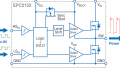
The inverter design consisted of three half bridges implemented using three daughter board modules. This approach had the advantage of simplifying and speeding up the testing of different switching technologies. This inverter featured six separate 55 mΩ switches, with CoolGaN 600 V enhancement-mode power transistor and CoolSiC 650 V in TOLL package device options, driven by EiceDRIVER 2EDF7175F dual channel gate drivers.
Low- and high-side bias voltages from an isolated supply on the main board were adjustable for the different wide bandgap technologies (SiC 18 V and GaN 10 V). To ensure precise control of the power switches in the motor drive inverter, XENSIV TLI4971 hall effect current sensors on the main board measured inverter phase currents. These signals were processed by an XMC XMC4400 microcontroller which also used position sensors to perform Field Oriented Control (FOC) of the Permanent Magnet Synchronous Motor (PMSM) speed.
Table 1. Permanent magnet synchronous motor parameters
| Parameters | BSM33C-6177MHQ |
| Voltage | 320 V |
| Current | 12.5 A |
| Power | 3 hp |
| Speed | 1800 rpm |
| Inductance | 5.2 mH |
| Resistance | 1 Ω |
An induction motor acted as an Eddy current brake with various currents applied to the windings of the induction motor in order to modify the shaft torque. Using an induction motor brake also ensures a smooth loading torque while preventing cogging.
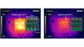
The board and test setup used to evaluate the impact of WBG switching devices are shown in Figure 1.

Figure 1. Test board and measurement equipment. Image used courtesy of Bodo’s Power Systems [PDF]
Inverter Power Losses
Energy is lost in a motor inverter when DC power is converted to AC. This is due to a combination of resistive losses in the inverter’s components, switching losses in the power electronic devices, and electromagnetic losses in the passive devices. The amount of energy lost depends on the inverter design and specifications and is directly related to the switching frequency of the inverter at which the inverter operates.
Higher switching frequencies increase the switching losses due to more switching events taking place. Therefore, selecting an appropriate inverter switching frequency is important in order to optimize the overall efficiency of the motor drive system. Ultimately, compromises are necessary in order to determine the optimal switching frequency for a specific motor-inverter setup. The power semiconductor device technology chosen to help reduce power loss in an inverter depends on numerous factors, including voltage, current, switching frequency, duty cycle, rate of change of voltage (dv/dt), and gate resistance (Rg).
Figure 2 shows simulated power losses (using PLECS) for 600-650 V rated GaN and SiC power switching devices operating at 320 V and 8 A from the lowest to the highest switching frequencies. SiC switches have a slight advantage over GaN at lower frequencies (5-10 kHz). However, from 20-50 kHz, GaN devices exhibit significantly lower power losses when compared to SiC. However, optimizing the performance and efficiency of the motor drive system requires power technology and device characteristics also to be considered.

Figure 2. PLECs simulated inverter losses for different switching devices across frequency. Image used courtesy of Bodo’s Power Systems [PDF]
Motor Power Losses
In this study, the focus was on motor high-frequency losses. Separating measurements into high-and low-frequency components was done using an iterative process of successive low-pass filters. Figure 3 shows the results of current measurements produced by discrimination. For voltage, a similar separation process is also applied.

Figure 3. Separating high- and low-frequency currents. Image used courtesy of Bodo’s Power Systems [PDF]

Figure 4. High-frequency current component. Image used courtesy of Bodo’s Power Systems [PDF]
Figure 4 shows the high-frequency phase current after current conditioning is performed. As expected, the magnitude of the current ripple is lower at higher switching frequencies, with this reduced current ripple also helping to reduce the amount of energy lost in the motor.
Motor Power Losses at High-Frequency Operation
High-frequency power losses in motor drives can be calculated using the following equation:
\[Lossess_{HF}=(V_{ab_{HF}}I_{a_{HF}}+V_{bc_{HF}}I_{b_{HF}}+V_{ca_{HF}}I_{c_{HF}}+V_{ab_{HF}}I_{b_{HF}}+V_{bc_{HF}}I_{c_{HF}}+V_{ca_{HF}}I_{a_{HF}})/3\]
High-frequency power losses at different switching frequencies for various motor rotational speeds are shown in Figure 5, where \(|I|=\sqrt{I^{2}_{d}+I^{2}_{q}}\). High-frequency losses at 900 rpm and 50 kHz are too small to be displayed.
The results demonstrate the clear impact of the switching frequency on the high-frequency motor losses, with high-frequency power losses being considerably reduced. The highest losses occur at 1800 rpm and 5 kHz. For this operating point, losses are approximately 12 W, while for the same speed and 50 kHz switching frequency, losses are only 2 W, representing a 10 W power saving.

Image used courtesy of Bodo’s Power Systems [PDF]

Image used courtesy of Bodo’s Power Systems [PDF]

Figure 5. High-frequency losses at various motor rotational speeds. Image used courtesy of Bodo’s Power Systems [PDF]
Another key result is that the high-frequency losses depend on the motor’s rotational speed, possibly due to increased eddy currents in the magnets at faster speeds. Iron losses are another feature that varies with speed, with hysteresis rising in line with motor speed, also impacting the amount of power loss in the motor.
Overall System Losses
Parameters, including load, speed, and temperature, influence the efficiency of a motor drive system. Reducing energy losses relative to the output power delivers optimum motor operating efficiency. An analysis of the combination of high-frequency motor and inverter losses (Figure 6) revealed that the optimum operating point (where the motor drive system exhibits the lowest losses relative to its output power) was achieved at a switching frequency of 20 kHz when running at a nominal speed of 1800 rpm and 50 percent rated load (1.1 kW).
Maintaining operation as close to this point as possible is vital to minimize power dissipation. Figure 6 confirms that the choice of the operating switching frequency requires evaluation at a system level. This choice involves consideration of the device technology used in the inverter and the motor. Using different switching technologies can alter the optimal operational switching frequency and the power losses experienced by the system.

Image used courtesy of Bodo’s Power Systems [PDF]

Figure 6. Determining overall system losses and optimum operating point. Image used courtesy of Bodo’s Power Systems [PDF]
WBG Switching Devices Summary
When using wide bandgap switching devices, motor drive systems operating at higher switching frequencies can deliver higher overall system efficiency. However, the switching frequency should be carefully selected because of the compromise between the inverter and the motor losses.
Experimental results showed that motor high-frequency power losses are reduced at higher switching frequencies. However, further analysis is required on the impact of the lifetime of motor bearings and windings at high switching frequencies and for faster transitions (dv/dt, di/dt). Furthermore, the impact of higher switching frequencies on low-frequency losses also requires further research.
New motor designs must consider the potential for WBG devices to meet future efficiency demands. Furthermore, future motor designs should also help address problems associated with higher switching frequency (e.g., wear and tear in bearings and windings, etc.).
References
1. A. K. Morya et al., “Wide Bandgap Devices in AC Electric Drives: Opportunities and Challenges,” in IEEE Transactions on Transportation Electrification, vol. 5, no. 1, pp. 3-20, March 2019, DOI: 10.1109/TTE.2019.2892807.
2. L. Chang, M. Alvi, W. Lee, J. Kim, and T. M. Jahns, “Efficiency Optimization of PWM-Induced Power Losses in Traction Drive Systems with IPM Machines Using Wide Bandgap-Based Inverters,” in IEEE Transactions on Industry Applications, vol. 58, no. 5, pp. 5635-5649, Sept.-Oct. 2022, DOI: 10.1109/TIA.2022.3178979.
3. L. Chang, W. Lee, T. M. Jahns, and K. Rahman, “Investigation and Prediction of High-Frequency Iron Loss in Lamination Steels Driven by Voltage-Source Inverters Using Wide-Bandgap Switches,” in IEEE Transactions on Industry Applications, vol. 57, no. 4, pp. 3607-3618, July-Aug. 2021, DOI: 10.1109/TIA.2021.3075647.
4. K. Yamazaki and A. Abe, “Loss Investigation of Interior Permanent-Magnet Motors Considering Carrier Harmonics and Magnet Eddy Currents,” in IEEE Transactions on Industry Applications, vol. 45, no. 2, pp. 659-665, March/April 2009, doi: 10.1109/ TIA.2009.2013550.
5. N. Voyer, G. Bueno Mariani, A. Besri, V. Quemener, Y. Okamoto and A. Satake, “High-Frequency Modelling of Permanent Magnet Synchronous Machine,” 2018 8th International Electric Drives Production Conference (EDPC), 2018, pp. 1-6, DOI: 10.1109/ EDPC.2018.8658271.
6. Dahaman Ishak, Z. Q. Zhu, and David Howe “Eddy-Current Loss in the Rotor Mag-nets of Permanent-Magnet Brushless Machines Having a Fractional Number of Slots Per Pole,” IEEE Transactions on Magnetics, Vol. 41, No. 9, September 2005.
7. F. Z. Zhou, J. X. Shen, and W. Z. Fei, “Influence on Rotor EddyCurrent Loss in High-Speed PM BLDC Motors,” Proceedings of the 41st International Universities Power Engineering Conference, Newcastle upon Tyne, UK, 2006, pp. 734-738, DOI: 10.1109/UPEC.2006.367576.
8. Pfingsten, G. & Steentjes, Simon & Thul, A & Herold, Thomas & Hameyer, K. (2014). “Soft magnetic material degradation due to manufacturing process: A comparison of measurements and numerical simulations.” 2014 17th International Conference on Electrical Machines and Systems, ICEMS 2014. 2018-2024. 10.1109/ICEMS.2014.7013817, Oct. 22-25, 2014, Hang-zhou, China
This article originally appeared in Bodo’s Power Systems [PDF] magazine.