Facebook
 Google
 GitHub
 Linkedin
Motor Starters Part 6: Variable Frequency Drives
Part 6 of the motor starter series introduces variable frequency drives and how they work to control torque, speed, and direction.
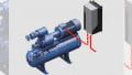
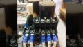
Drives are deployed to help control torque, speed, and direction. In most cases, drives are good for motion or speed control in power systems applications such as robots, transportation, fans, machine tooling, etc.
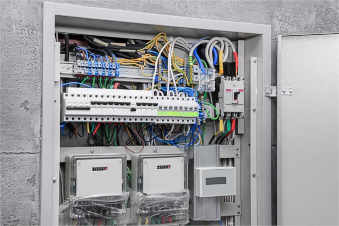
Image used courtesy of Adobe Stock
Electric drives, which can be variable or constant, are used to control electric motors. When the motor operates under variable speeds, constant speed drives cannot be deployed, and variable speed drives take charge. This article will focus on Variable Frequency Drives (VFD), also known as AC or variable speed drives.
Why Use Electric Drives?
When using an application that does not need to run at full speed, variable frequency drives can cut the cost of energy consumed. The purpose of the VFD is to match the speed of the equipment driven by the motor to that of the required load. This cannot be attained by other AC electric drives.
In industry, 65% of electricity consumption is from electric motors. This consumption can be reduced by optimizing the motors using VFDs, which reduce consumption by 70%.
To ensure the motor operates at the most efficient speed and accuracy in order to increase the level of production, variable frequency drives are recommended.
Controlling equipment using VFDs gives them a longer life and fewer maintenance requirements as they attain appropriate motor speed. The VFD controlling motor frequency and voltage offers the best protection against overloads, under voltage, and overvoltages.
Types of VFDs
Three types of VFDs exist: Voltage-Source Inverter (VSI), Current-Source Inverter (CSI), and Pulse Width Modulation Inverter (PWM).
VSI is the most common type of VFD, where a simple diode circuit is used to get the DC signal from the AC signal and has a capacitor that stores energy. An inverter circuit then uses the energy stored by the capacitor to deliver it to the output.
CSI depends on the current instead of the voltage and produces a smooth output that depends on the variable voltage range. A thyristor bridge inverter is used in place of the diode bridge rectifier to generate a current square wave.
How VFDs Work
With VFDs, the motor’s rotation speed is controlled via the frequency of the input voltage before it is supplied to the motor. The first action of the AC drive is converting 60 Hz, 3-phase AC power to DC before inverting the DC power into a pseudo-three-phase variable frequency that goes directly into the connected motor.
The frequency approaching the electric converter is 60 Hz, but the one going out of the converter into the motor has an adjustable variable frequency for achieving the required motor speed.
The converter and the inverter form the two main parts of the PWM AC drive.

Figure 1. VFD working block diagram. Image used courtesy of Simon Mugo
The AC power line constitutes a three-phase power system that powers the converter. The AC power lines operate at 60 Hz frequency.
The converter utilizes a rectifier to convert the 60 Hz AC input into DC output voltage.
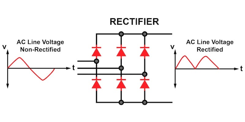
Figure 2. Converter part working diagram. Image used courtesy of Simon Mugo
The DC output delivered by the electric converter is rough; therefore, smoothening methods must be used to ensure a more or less constant output DC voltage. This filtering action occurs between the stages of conversion and inversion. After smoothening, the DC is sent directly into the inverter stage.
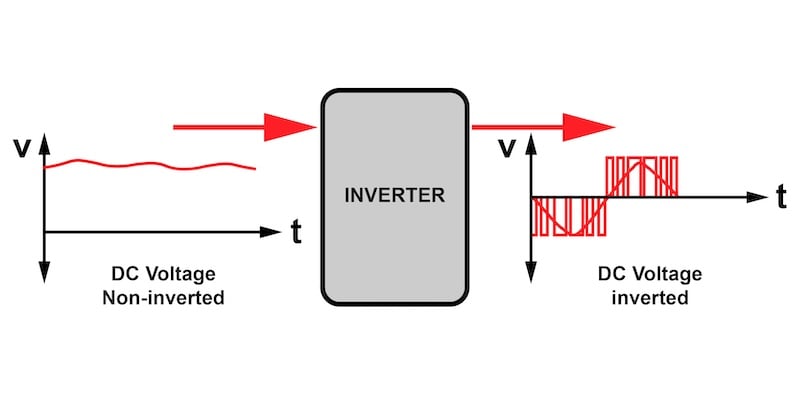
Figure 3. Inverter part working diagram. Image used courtesy of Simon Mugo
The purpose of the inverter section is to produce AC output that is tapped to drive the motor. The negative and positive switching occurs in the inverter, resulting in a collection of pulses.
The PWM drive output frequency is controlled by injecting positive pulses on one of the half cycles and negative pulses on the half cycle that follows the first.
The sine wave output consists of narrow and wider sine waves. The narrow represents the lower output voltage values, while the wider represents higher voltage values. The varying widths are what make Pulse Width Modulation. The diagram shows six pulses per every half cycle.
Magnetic Flux–Volts-Per-Hertz Ratio
Applying current to the induction motor causes the motor to generate magnetic flux in the rotating field and, hence, produce torque. For full-load torque production, the magnetic flux must be retained at a constant. Controlling the motor at a constant magnetic flux requires a special method known as the volts-per-hertz ratio. This method makes voltage and frequency increase proportionally at the same value to produce good motor torque.
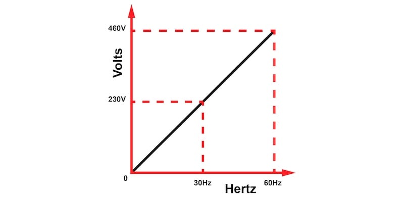
Figure 4. The ratio of voltages per hertz. Image used courtesy of Simon Mugo
For example, if the voltage is 430 V and the frequency is 60 Hz, the volts-per-hertz ratio is 430/60 or 7.2 V/Hz.
The VFD works to maintain the voltage and frequency ratio at a constant. If it fails to maintain this constant, the motor current becomes unstable, which can diminish torque.
Motor Speed
Motor speed can be calculated using the formula
\[Speed(RPM)=Frequency(Hz)\times\frac{120}{n}\]
Where
\[n=number\,of\,poles\]
For example, having a 2-pole motor at 60 Hz frequency, speed can be determined by
\[Speed(RPM)=60\times\frac{120}{2}=3600RPM\]
VFD Benefits
- Saves energy
- Consumes very low motor starting currents
- Simple to install
- Consumes low KVA
- Has a relatively high power factor
- Reduces mechanical and thermal stress on belts and motors during starting
VFD Applications
- Material transferring on the conveyor belt because it offers the smoothest starting.
- Automatic systems to open and close the gates since VFD operations have minimal noise
- Hoist control and lifting of the materials due to reduced power consumption, less maintenance, and longer equipment life.
Key Takeaways of Variable Frequency Drives
- Electric AC drives are used to control moving objects’ torque, speed, and direction.
- Electrical AC drives are classified as variable or constant with variable drives used for motors operating under variable speeds.
- Reasons for using electrical AC drives are reduced energy costs and consumption, increased production due to tighter process control, increased equipment life, and reduced maintenance.
- VFDs use frequency to control the speed of the motor, where the frequency of the input signal is controlled before being injected into the motor.
- VFDs are used in conveyor belts for smooth starting, as automatic systems to open and close the gates, and as hoist control for lifting materials.