Facebook
 Google
 GitHub
 Linkedin
The Power Module That Stabilizes the Grid
Maintaining a stable grid frequency is more important than ever, and demand for energy storage devices is growing. A crucial element of an effective energy storage system is the power conversion system, which acts as an interface between the direct current batteries and the grid. This article discusses a specially designed technology intended for use in high-power systems.
This article is published by EEPower as part of an exclusive digital content partnership with Bodo’s Power Systems.
In modern power grid systems, maintaining a stable grid frequency is more important than ever due to new challenges, such as the transition to renewable energies. This is largely due to the significant amount of energy consumed in today’s world and governmental goals to reduce carbon emissions. Consequently, the demand for energy storage devices is growing. A crucial element of an effective energy storage system (ESS) is the power conversion system (PCS). The PCS acts as an interface between the direct current (DC) batteries and the electrical grid.
A power conversion system (Figure 1) is equipped with a power semiconductor module as its main component, which connects the energy storage battery system to the power grid to enable bidirectional conversion of electrical energy. When there is excessive power generation, the PCS charges the batteries. If the grid requires additional energy, the PCS supplies the stored energy. Additionally, it provides inertia energy to maintain the grid frequency close to 50/60 Hz. This can be achieved with a mechanical solution like a flywheel, which stores energy by spinning a mass with a moment of inertia. These energy storage systems are typically large and heavy but can release a high amount of energy in a short time. Such systems can reach up to 100+ kW, and more units can be connected in parallel if more power is needed.
A more modern solution is battery storage systems, also known as energy storage systems, with the PCS as the main component for energy conversion. Any type of battery can be used, but Lithium-ion batteries are preferred due to their higher power density and longer lifespan compared to lead-acid batteries. Since megawatts of power are required, these systems can be built from several smaller units or a single large one. This article discusses a specially designed product intended for use in high-power systems.
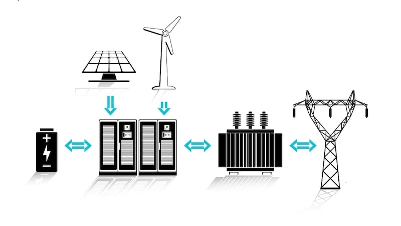
Figure 1. Power conversion system. Image used courtesy of Bodo’s Power Systems [PDF]
A stable grid frequency around 50/60 Hz is necessary for the correct operation of many devices. This is especially true for older devices that generate their internal operating frequencies and timings from the grid frequency. However, modern devices use DC/DC power supplies and generate frequencies from internal oscillators or receive synchronization signals from servers.
VINcoX 3-Level High Power Module
VINcoX modules are specifically designed for uninterruptible power supply (UPS) and ESS applications ranging from 160 kW to 1.4 MW, depending on operating conditions. They are optimized for bidirectional operation, essentially a platform consisting of up to three power modules connected by a high-power PCB. All main potentials are shared on the PCB, resulting in decreased stray inductance.

Figure 2. VINcoX12 power module. Image used courtesy of Bodo’s Power Systems [PDF]
Two topologies are available: a 3-level T-type with 1200 V and 650 V components for 1000 V systems, which can be provided with snubber capacitors as an option, and an I-type with 1200 V components for DC-links exceeding 1500 V. Switching frequencies are relatively low in this power range, so semiconductors with low conduction loss are used—in this case, the Mitsubishi M7. Alongside a low VCEsat, it offers superior H3TRB capability.
A Symmetrical Layout
A challenge with larger power modules is that many semiconductors need to be switched in parallel. All devices should switch simultaneously to achieve good current sharing. Long connections inside the power module could result in turn-on and turn-off delays, causing uneven loads on chips. Therefore, each of the three segments has its own gate-emitter connections. Furthermore, each commutation loop on the DCB has its own connections. The driver PCB, which can be pressed or soldered to the press-fit pins, needs to manage these signals. Design hints and layout recommendations are provided in the evaluation driver board documentation.

Figure 3. Turn-off waveform of an 1800 A module @ IC = 3200 A at ambient temperature. Image used courtesy of Bodo’s Power Systems [PDF]
The turn-off waveform in Figure 3 is measured with the largest available VINcoX12 module, featuring a nominal chip current of 1800 A (model 70-W624NIA1K8M701-LD00FP70). This module has 100% rated components in all positions, making it an ideal choice for 4Q operation. As shown, the module has very low stray inductance and can be switched quite aggressively with a 0.5 Ω gate resistor, resulting in an overvoltage spike of only 41%, which is approximately 990 V for a 1200 V semiconductor.

Image used courtesy of Bodo’s Power Systems [PDF]
Reliability
Reliability is critical for many applications, so this module does not use a single large copper baseplate but instead has two baseplates per segment (Figure 4). This design means a VINcoX12 module consists of six baseplates. These are decoupled from each other, resulting in less absolute thermal expansion compared to a single baseplate, which reduces mechanical stress on the thermal interface material.
For many applications, thermal reliability is of particular interest. Heavy load changes stress the chip/bond wire connections and the solder material between the chip and DCB. Additionally, operating at high loads and high chip temperatures may degrade the chip solder material if it becomes too hot. The new advanced solder material contributes to both, resulting in a significantly longer lifetime. It enhances the power cycling capability by nearly two times and the high-temperature forward bias capability by up to nine times.

Figure 4. PCs capability and VINcoX12 backside. Image used courtesy of Bodo’s Power Systems [PDF]
Inertia for Energy Storage
VINcoX modules are specifically designed for 3-level high-power applications, primarily for energy storage systems to provide inertia energy. With 100% rated components in all positions, they are ideal for applications requiring bidirectional operation. The flexibility to add up to three segments allows for coverage of chip current ratings between 400 A and 2400 A. T-type and I-type topologies are available for both 1000 V and 1500 V systems. The blocking voltage capability of the I-type topology with 1200 V components allows for even higher DC-link voltages. High reliability and long lifespan are achieved by using two separate baseplates per segment and advanced solder material for superior power cycling and high-voltage forward bias capability. As an option, modules can be delivered with pre-applied phase-change material to eliminate the thermal pasting process in the customer’s production area. Overall, the VINcoX platform is suitable for all 3-level applications ranging from 200 kW to 1.5 MW.
This article originally appeared in Bodo’s Power Systems [PDF] magazine.