Facebook
 Google
 GitHub
 Linkedin
How Do Smaller FRDs Improve IGBT Performance in UPS PV Inverters?
This article examines the use of fast recovery diodes in photovoltaic inverters for uninterruptible power supplies.
This article is published by EEPower as part of an exclusive digital content partnership with Bodo’s Power Systems.
Photovoltaic (PV) inverters for uninterruptible power supplies (UPS) are one of the most popular applications of discrete IGBTs. This application has a higher power factor (PF) operating condition (PF ~ 1.0) for which a smaller fast recovery diode (FRD) can provide better performance. The smaller FRD has higher reverse conduction loss but contributes to Err and Eon reduction. Thus, total power loss is better than a larger FRD configuration.
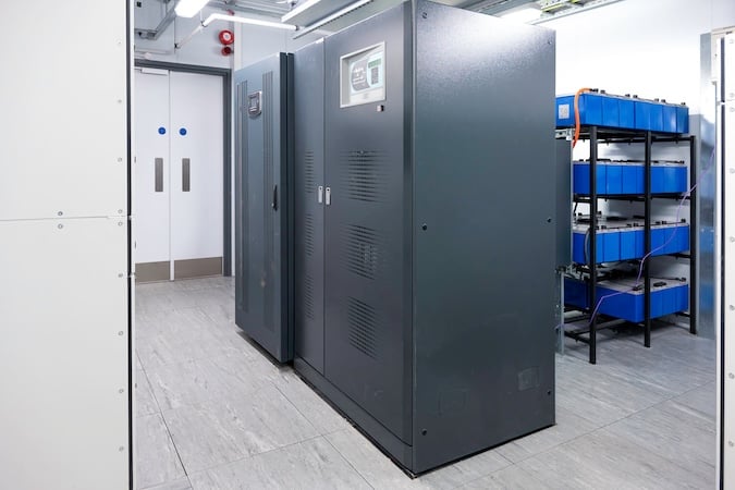
Image used courtesy of Adobe Stock
Discrete IGBTs
A range of IGBT products are utilized in the power electronics market, especially in the industrial power converter market, where many discrete packaged products are implemented. Almost all discrete IGBT products have a co-pack diode in the same package for reverse current conduction.
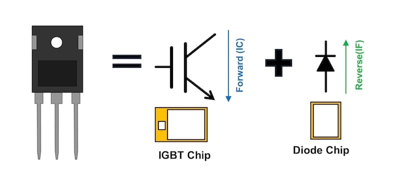
Figure 1. IGBT diode co-pack device. Image used courtesy of Bodo’s Power Systems [PDF]
The diode is mandatory for IGBT in inverter applications, which require reverse current conduction to power devices. IGBT characteristics are very important for the efficiency of the inverter circuit, but the co-pack diode is also important for the performance and the overall device cost.
What Is the Current Rating of Discrete Devices?
Power devices have absolute maximum ratings for voltage, current, and temperature. Renesas has a dedicated application note for each parameter definition. Design engineers refer to “collector current IC” and “diode forward current IF” individual ratings to find the correct device for their application. However, in practice, comparing the maximum current in the application with IC and IF is not meaningful. Those current ratings are DC ratings defined by the below formula. The actual current in inverter applications is not DC.
\[I_{C}\frac{(Tjmax-Tc)}{R_{th(j-c)}\times V_{CE(sat)}}\]
Equation 1. DC rating definition.
IGBT and diode can support higher current than the IC & IF ratings as long as the junction temperature does not exceed the junction temperature rating (Tj max) and peak current does not exceed IC(peak) or IF(peak).
UPS and PV Inverter Operating Conditions
The UPS and PV (PV) markets are growing rapidly, as both contribute to carbon dioxide emissions reduction and have inverter circuits requiring high-voltage switch solutions, such as discrete IGBTs.
In inverter circuits, IGBTs (and diodes) work with the PWM gate control. Their conduction duty is dependent on the PF. In Figure 2, the blue area shows IGBT conduction duty, and the green area shows diode duty. As depicted in Figure 2, They have the same duty under the PF=0 condition, and the IGBT conduction area is bigger than the diode in cases where PF>0.
In the UPS and PV inverter applications case, PF is nearly +1.0 and never goes to the PF<0 condition. This means that the diode’s forward voltage, which contributes to conduction loss, has minimal impact on the performance of UPS and PV systems. On the other hand, switching loss and diode recovery loss are independent of the power factor (PF) and are instead influenced by the switching frequency.
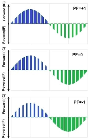
Figure 2. PF dependency of IGBT and diode conduction duty. Image used courtesy of Bodo’s Power Systems [PDF]
Power Loss in Fast Recovery Diodes
Conduction loss by VF and recovery loss by Qrr are the power loss factors in diode characteristics. They are in a trade-off relationship, such that if we design the diode to focus on low recovery loss, it affects forward voltage and vice versa. Both power losses depend on chip size. Generally speaking, a bigger chip has lower VF and higher Qrr. Chip size directly relates to the IF rating.
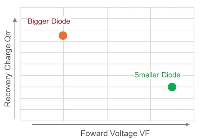
Figure 3. Chip size dependency of diode characteristics. Image used courtesy of Bodo’s Power Systems [PDF]
Qrr impacts the IGBT turn-on loss. The basic half-bridge configuration is shown in Figure 4. The high-side diode is in a conduction state before the turn-on of the low-side IGBT. Then, the recovery current appears in the turn-on current waveform, affecting turn-on loss.
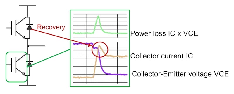
Figure 4. Turn-on waveform recovery affects turn-on loss. Image used courtesy of Bodo’s Power Systems [PDF]
This indicates that for UPS and PV inverters, a smaller co-pack diode rating than the IGBT might be more suitable, as the diode’s conduction duty is lower than that of the IGBT. A smaller diode can help reduce recovery and IGBT turn-on loss.
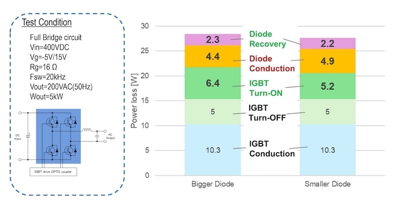
Figure 5. Total power loss simulation conditions and results. Image used courtesy of Bodo’s Power Systems [PDF]
G8H Concept
Renesas investigated to determine the optimal diode size for UPS and PV applications. Renesas simulated the total power loss of the IGBT and diode based on an evaluation of switching characteristics. The device is a 650 V 50 A class IGBT. Two different co-pack diode sizes, 30 A (smaller) and 50 A (larger), were evaluated with the IGBT with the same voltage class. Those current classes refer to the IC and IF rating.
As you can see in Figure 5, the IGBT + smaller diode configuration shows smaller power loss thanks to low recovery loss and low turn-on loss. Even though diode conduction loss is higher, the smaller diode can contribute a 2.5% improvement in efficiency. Diode chip costs of up to 20% can be saved with a smaller chip for a good cost and performance-balanced solution.
Note that a smaller chip has a smaller IF rating and higher thermal resistance, but the power loss of the diode is sufficiently small due to low duty (Figure 2) and Tj of the diode that it does not exceed its Tj maximum rating. Based on this result and application requirements, Renesas has optimized its IGBT product lineups, as shown in Table 1, where the co-pack diode has a smaller current rating than the IGBT for better performance in UPS and PV applications.
Table 1. Renesas G8H series lineups
|
Part Number |
VCES [V] |
IC [A] |
IF [A] |
|
RBN25H125S1FPQ-A0 |
1250 |
25 |
15 |
|
RBN40H125S1FPQ-A0 |
1250 |
40 |
25 |
|
RBN75H125S1FP4-A0 |
1250 |
75 |
50 |
|
RBN40H65T1FPQ-A0 |
650 |
40 |
30 |
|
RBN50H65T1FPQ-A0 |
650 |
50 |
50 |
|
RBN75H65T1FPQ-A0 |
650 |
75 |
50 |
Takeaways
The inverter circuits in UPS and PV applications are operated under high PF conditions. Diode conduction duty is low in high PF operation, so a smaller diode should be better for circuit efficiency. Renesas confirmed by power loss simulation. A smaller diode contributes to total performance as well as cost improvement. Furthermore, a smaller diode has higher thermal resistance, but power loss is low enough in high PF operation to keep a lower junction temperature than the Tj max rating. So, a smaller IF rating diode can work with a higher IC rating IGBT.
Renesas G8H series is focused on UPS and PV applications. The lineup includes smaller diodes to improve cost and efficiency. Renesas’s next-generation IGBT discrete series is currently under development. Renesas has plans for a larger lineup to support additional applications, such as UPS, PV, EV charging systems, motor drives, and more, while keying in on further performance improvement.
This article originally appeared in Bodo’s Power Systems [PDF] magazine and is co-authored by Shinya Ishida and Hiroki Ando, High Voltage Product Application Engineering with Renesas Electronics.