Facebook
 Google
 GitHub
 Linkedin
Power Transfer and Angle Stability in Long-Distance Power Transmission
In this article, we will examine power transfer and angle stability. This is the final article in a 3-part series on long transmission line behavior.
The first two articles in this series examined surge impedance and wave propagation. We now turn our attention to topics that include the impact of line impedance and length on angular stability.
The fundamental equation governing real power transfer over a transmission line between two buses (sending and receiving ends) is derived from the basic power flow expression:
$$P = \frac{EV}{X} \sin \delta$$
Where:
- P is the real power transmitted,
- E and V are the sending and receiving end voltages (assumed constant),
- X is the total series reactance of the line,
- δ is the load angle between the two voltage phasors.
This sinusoidal power-angle (P–δ) relationship reaches a maximum at δ = 90°, beyond which stability cannot be maintained. In long transmission lines, the reactance X becomes large due to increased line length and the distributed nature of the line impedance. This directly reduces the maximum power transfer \[P = \frac{EV}{X}\] and thus constrains the operating angle δ for a given power flow requirement.
For long lines, particularly above 250 km in length, the lumped X approximation becomes less accurate. Instead, transmission behavior is governed by the distributed line model, where the power flow equation generalizes to:
$$P = \frac{EV}{Z_0} \sin (\beta l)$$
Where:
- \[Z_0 = \sqrt{\frac{L}{C}}\] is the surge impedance,
- \[ \beta = \omega \sqrt{LC} = \frac{2 \pi}{\lambda} \] is the phase constant,
- l is the line length,
- \[\omega = 2 \pi f\] is the angular frequency.
This formulation reveals that the sinusoidal P–δ characteristic for short lines evolves into a wavelength-dependent relationship for long lines, especially when the line approaches a quarter-wavelength in electrical length, where power transfer behavior becomes resonant.
Impact of Line Impedance and Length on Angular Stability
As line length increases, the cumulative inductive reactance, \[X = \omega L \cdot l\] grows proportionally. This increased reactance weakens the coupling between generators and loads, making the system more susceptible to angle instability during transients such as faults or switching.
This has two primary implications:
- Reduced Synchronizing Torque: For a small change in angle δ, the rate of change of electrical power \[\frac{dP}{d \delta}\] (known as synchronizing power) decreases with larger X, reducing the ability of the system to restore synchronism after disturbances.
- Lower Stability Margin: A given power flow will correspond to a higher δ on a weaker line. Operating closer to the critical max (often ~90°) increases the risk of loss of synchronism under perturbation.
Therefore, long-distance power transfer requires additional support mechanisms such as series compensation, FACTS devices, or generation redispatch to maintain acceptable angular margins.
Equal Area Criterion Applied to Long Transmission Lines
The equal area criterion (EAC) provides a graphical method to assess transient stability for a simple two-machine system or an equivalent single-machine-infinite-bus (SMIB) system. It evaluates whether the accelerating energy gained by the generator during a disturbance can be offset by the decelerating energy during system recovery.
For a line experiencing a temporary fault (such as 3-phase fault cleared after time tc ), the EAC involves comparing two areas under the power-angle curves:
$$\text{Area }A_1 = \int_{\delta_0}^{\delta_c} \big(P_m - P_e(\delta) \big) d \delta$$
$$\text{Area }A_2 = \int_{\delta_c}^{\delta_{max}} \big(P_e(\delta) -P_m \big) d \delta$$
Where:
- Pm is the mechanical power,
- 0 is the pre-fault angle,
- c is the angle at fault clearing,
- max is the angle where kinetic energy is fully absorbed.
For a long transmission line, the post-fault Pe(δ) curve is shallower due to increased reactance, shrinking the decelerating area A2. This means that for the same disturbance duration, a long line may lead to instability unless compensated or unless fault clearing is sufficiently fast.
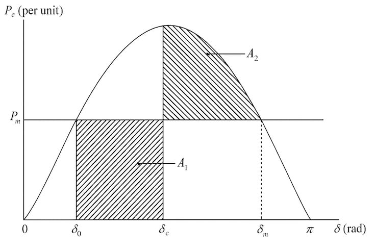
Power-angle curve for equal area criterion. Image used courtesy of NPTEL
Interaction with Generator Dynamics and AVR/PSS
The dynamic response of the power system to angular disturbances is significantly influenced by generator control systems, particularly the Automatic Voltage Regulator (AVR) and the Power System Stabilizer (PSS). While AVR enhances voltage regulation by modifying excitation, its fast action can introduce negative damping in rotor oscillations if not properly coordinated.
The PSS is designed to counteract this by injecting a stabilizing signal into the AVR, proportional to the rotor speed or power output derivative, to damp out electromechanical oscillations.
For long lines, where the weak electrical coupling exacerbates oscillatory behavior, tuning the AVR and PSS gains becomes more critical. Uncoordinated settings can lead to local or inter-area oscillations, particularly when multiple generators are exporting power over extended corridors. Moreover, the presence of series capacitors or FACTS devices on long lines can shift the natural frequency of oscillations, requiring retuning of PSS parameters to maintain system damping.
Advanced transient stability analysis often couples the transmission line model with detailed generator models (such as IEEE Type-1 or Type-3 exciters) in simulation environments like PSSE, DIgSILENT PowerFactory, or EMTP-RV to evaluate these interactions.
Key Takeaways
In modern power systems, accurate modeling and understanding of long transmission lines are essential for ensuring both operational reliability and optimal power transfer. The distinct behavior of long lines—including distributed parameter effects, surge impedance loading, wave propagation, and angle stability—directly influences how systems respond to disturbances, load variations, and control actions.
These characteristics are not only essential to voltage profile management and overvoltage mitigation but also play a critical role in system planning, protection coordination, and the integration of renewable resources over vast distances. As grids become more interconnected and dynamic, incorporating detailed long-line models into simulation tools and stability assessments becomes increasingly vital for secure and efficient grid operation.
Featured image used courtesy of Adobe Stock (licensed)