Facebook
 Google
 GitHub
 Linkedin
Electric Motor Sizing and Selection Explained
The article guides electrical engineers on electric motor sizing and selection to satisfy their power system requirements.
For an electric power system to work well, the secret lies in the proper sizing and selection of important components. Sizing and properly selecting an electric motor goes a long way to improve reliability and performance while making equipment cost-effective. This article will guide you through selecting and sizing an electric motor.
Determining the Motor Drive Mechanism
The first step is determining the motor drive mechanism. The drive mechanism includes a belt drive, shaft, direct rotation, pulley, ball screw or rack, and pinion.
While determining the drive mechanism, also decide the dimensions, which are important for motor sizing:
- Load dimensions and mass
- Each part’s dimension and mass
- Coefficient of friction of each moving part sliding surface
The next step is determining the motor’s parameters and specifications, including:
- Operating time and speed
- Positioning distance and time
- Resolution
- Stopping accuracy
- Voltage and power supply
- Position holding
- Environment of operation
- Specific requirements and features like closed loop, open loop, feedback, programmable, agent approval, and IP rating
To determine motor performance, establish the following three factors:
- Motor speed
- Motor torque
- Moment of inertia
Once the above three factors are calculated, the motor will be selected depending on the values obtained for speed, inertia, and torque. A range of of motors exists to choose from, such as servo, AC, stepper, and brushless motors.
Sizing the Motor: Calculations
For successful motor sizing, three important factors must be determined: torque, inertia, and speed.
Determining the Moment of Inertia
Moment of inertia is the measure of any given object’s resistance to its rotation rate changes. An object at rest has a zero moment of inertia.
Trying to move an object focuses on changing its speed from point zero to any level. This is accompanied by the change in the moment of inertia.
The Fundamental Equation of Inertia(J)
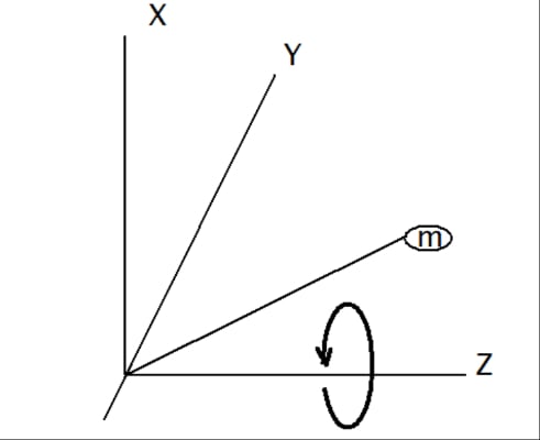
Figure 1. Fundamental equation of inertia diagram. Image used courtesy of Simon Mugo
\[J=\smallint\smallint\smallint \rho(x,y,z)(x^{2}+y^{2})dxdydz\]
Rotating Object Moment of Inertia Calculation
J = mL2
Where
m = mass
L = The distance between the center of rotation and the center of gravity.
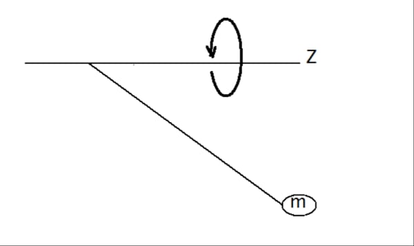
Figure 2. Diagram for rotating object moment of inertia calculation. Image used courtesy of Simon Mugo
Calculating the Cylinder’s Moment of Inertia
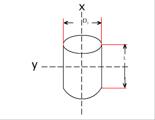
Figure 3. Solid cylinder. Image used courtesy of Simon Mugo
From Figure 3, the formula for calculating the moment of inertia for the solid cylinder can be derived as:
\[J_{x}=\frac{1}{8}mD_{1}^{\,\,\,2}=\frac{\pi}{32}\rho LD_{1}^{\,\,\,4}\]
And
\[J_{y}=\frac{1}{4}m(\frac{D_{1}^{\,\,\,2}}{4}+\frac{L^{2}}{3})\]
Where
Jx= inertia along x - axis
Jy = Inertia along y - axis
m = mass of the cylinder
D1 = The Cylinder Outer Diameter
ρ = Density of the Cylinder
L = Height of the Cylinder
Calculating the Hollow Cylinder Moment of Inertia

Figure 4. Hollow cylinder. Image used courtesy of Simon Mugo
From Figure 4, the formula for calculating the moment of inertia for the hollow cylinder which leads to the leading nations can be derived as:
\[J_{x}=\frac{1}{8}m\Big(D_{1}^{\,\,\,2}-D_{2}^{\,\,\,2}\Big)=\frac{\pi}{32}\rho L(D_{1}^{\,\,\,2}-D_{2}^{\,\,\,4})\]
And
\[J_{y}=\frac{1}{4}m(\frac{D_{1}^{\,\,\,2}-D_{2}^{\,\,\,2}}{4}+\frac{L^{2}}{3})\]
Where
Jx = inertia along x - axis
Jy = Inertia along y - axis
m = mass of the Hollow cylinder
D1 = The Hollow Cylinder Outer Diameter
D2 = The Hollow Cylinder inner diameter
ρ = Density of the Hollow Cylinder
L = Height of the Hollow Cylinder
An Off-Center Axis Moment of Inertia Calculation
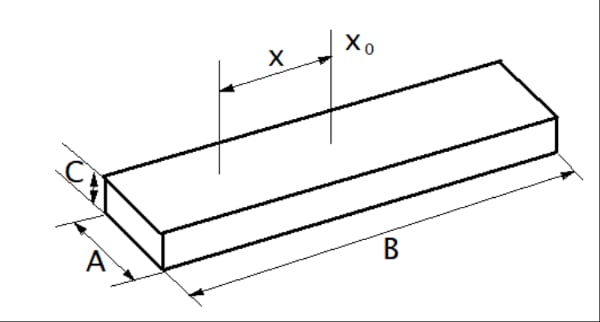
Figure 5. Off-Centre Axis Moment of Inertia
The following equations are necessary for calculating the off-center moment of inertia:
\[J_{x}=J_{x_{0}}+ml^{2}=\frac{1}{12}m(A^{2}+B^{2}+12l^{2})\]
Where
Jx = inertia along x - axis
Jy = Inertia along y - axis
J\(_{x_{0}}\) = Inertia along x0 - axis passing through the centre of gravity
m = mass
A = Width
B = Length
C = Height
ρ = Density
l = Distance between x and x0
Rectangular Pillar Moment of Inertia Calculation
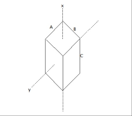
Figure 6. Rectangular pillar. Image used courtesy of Simon Mugo
The formula below will help solve the moment of inertia for the rectangular pillar above in Figure 6:
\[J_{x}=\frac{1}{12}m\Big(A^{2}+B^{2}\Big)=\frac{1}{12}\rho ABC\Big(A^{2}+B^{2}\Big)\]
And
\[J_{y}=\frac{1}{12}m\Big(C^{2}+B^{2}\Big)=\frac{1}{12}\rho ABC\Big(C^{2}+B^{2}\Big)\]
Where
Jx = inertia along x - axis
Jy = Inertia along y - axis
m = mass
A = Width
B = Length
C = Height
ρ = Density
Object in Linear Motion Moment of Inertia Calculation
\[J=m(\frac{A}{2\pi})^{2}\]
Where
A = Units of Moment
m = mass
Moment of Inertia Units of Measure
The units of inertia can be used in two ways: oz-in-sec2 and oz-in2. The former has an inclusion of mass while the latter involves gravity only.
Theoretically, the moment of inertia is a factor of mass only but, practically, inertia is affected by gravity; hence, one cannot ignore the effect of the earth’s gravity.
Gravity = 386 in/sec2
To convert oz-in2 to oz-in-sec2 take:
\[\frac{oz-in^{2}}{386\,in/sec^{2}}=oz-in-sec^{2}\]
Determining the Torque Required
Torque is the ability of a force exerted on an object to make the object rotate. Torque is a combination of two elements: acceleration and load elements. Load torque is caused by friction. Acceleration torque is available only when the motor is in rotation. When the motor is running at a constant speed, the component disappears.
Load Torque (T)
Torque is a product of force and the distance between this force and the center of rotation.
\[T=Fr=\frac{FD}{2}\]
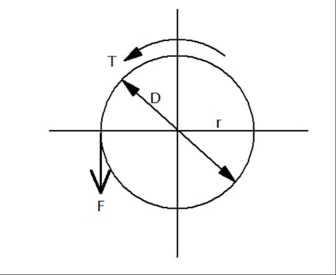
Figure 7. Load torque diagram. Image used courtesy of Simon Mugo
Actual Measurement of the Load Torque
The most accurate force is obtained by measuring, since it improves efficiency and gives an accurate coefficient of friction.
FB = Force at the start of rotation of the main shaft:
\[T_{L}=\frac{F_{B}D}{2}\]
Where
D = Pulley final diameter and g = acceleration due to gravity
Force
Three types of force need to be determined: vertical, inclined, and horizontal.
Calculating Vertical Force
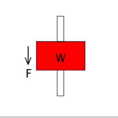
Figure 8. Vertical force. Image used courtesy of Simon Mugo
F = W = mg
Calculating Horizontal Force
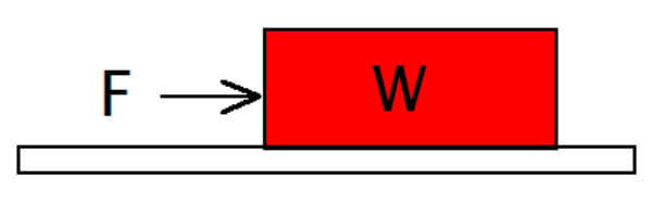
Figure 9. Horizontal force. Image used courtesy of Simon Mugo
F = μW
Calculating Inclined Force
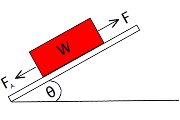
Figure 10. Inclined force. Image used courtesy of Simon Mugo
F = FA + mg(sinα + μ cosα)
Where
F = Moving direction force
μ = Friction coefficient of the sliding surface
g = gravity
m = mass of the table and load
FA = External Force
Ball Screw Driver Load Torque Calculation
\[T_{L}=(\frac{FP_{B}}{2\pi\eta}+\frac{\mu_{0}F_{0}P_{B}}{2\pi})\frac{1}{i}\]
\[F=F_{A}+mg(sin\theta+\mu cos\theta)\]
Where PB is the ball screw lead.
Pulley Drive Load Torque Calculation
\[T_{L}=\frac{(\mu F_{A}+mg)D}{2i}\]
Torque Calculation Equations for Belt or Wire Drive
\[T_{L}=\frac{F}{2\pi\eta}\times\frac{\pi D}{i}=\frac{FD}{2\eta i}\]
\[F=F_{A}+mg(sin\theta+\mu cos\theta)\]
Where
i = gear ratio
Acceleration Torque
Acceleration torque is made up of acceleration rate and inertia. By knowing the two values, acceleration torque can be calculated.
Ta = JA
Where
Ta = Acceleration torque
A = Acceleration Rate
J = Inertia
Speed
The speed of any particle is determined by measuring the distance it travels and dividing it by the time it takes to cover the distance.
For the stepper and servo motors, accounting for acceleration time is a must.
\[Speed=\frac{Distance}{Time}\]
Featured image used courtesy of Adobe Stock