Facebook
 Google
 GitHub
 Linkedin
Protecting Motor Feeders From Short Circuits and Ground Faults
Learn how to protect motor feeders and other loads against short circuits and ground faults.
Protecting the feeders to several motors and other loads against short circuits and ground faults is central for preventing damage, ensuring safety, maintaining electrical system stability, and extending equipment lifespan.
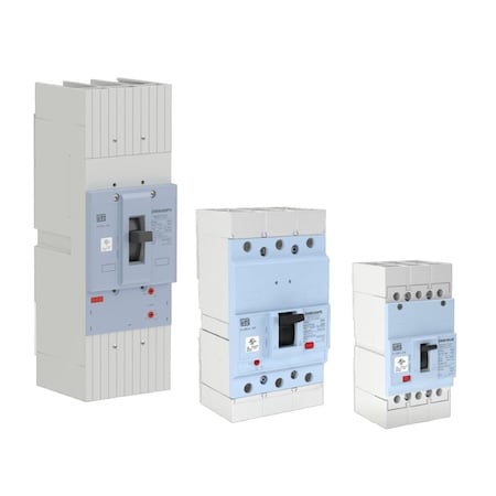
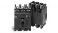
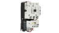
Image used courtesy of WEG
NEC Article 430. Part V Motor Feeder Short-Circuit and Ground-Fault Protection
NEC Section 430.61 General
The provisions of Part V specify protective devices to protect feeder conductors supplying motors against short circuits or ground faults.
.
NEC Section 430.62 Rating or Setting - Motor Load
Section 430.62(A) Specific Load
- Provide a device for overcurrent protection to a feeder supplying a fixed motor load(s) through conductors sized per Section 430.24, which allows an ampacity of 125% of the rating of the full-load current of the largest motor plus 100% of the full-load current rating of the other motors of the group.
- The overcurrent device’s rating or setting shouldn’t be greater than allowed for the largest branch-circuit short-circuit and ground-fault protection for any motor supplied by the feeder (as figured from Section 430.52, or Section 440.22(A) for the hermetic refrigerant motor-compressors) and the sum of the full-load currents of the other motors.
- For the above calculations, consider only one of the protective devices as the largest if more than one of the branch circuits supplied by the feeder uses the same rating or setting for the short-circuit and ground-fault protective device.
- Do not apply the rule in Section 430.52(C)(1)(a), which permits the use of the next-size-up protection for branch circuits to motor feeder overcurrent protective devices when the maximum rating does not match a standard size.
If the protective devices used for feeder and branch-circuit protection are of different types, e.g., a circuit breaker and a fuse, assume that they are the same type to size the feeder protective device.
Example 1: Figure 1 shows a 208-V, three-phase, four-wire feeder in an industrial plant feeding five 200-V, three-phase, general-purpose, continuous-duty induction motors as follows:
- 1 x 40-hp wound-rotor
- 2 x 25-hp squirrel-cage
- 1 x 10-hp squirrel-cage
- 1 x 5-hp squirrel-cage
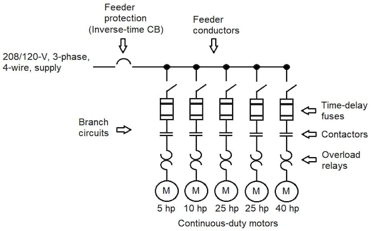
Figure 1. Set-up for Example 1. Image used courtesy of Lorenzo Mari
a) Find the motor full-load currents from tables.
b) Find the minimum acceptable feeder conductor ampacity.
c) Would the method to compute the minimum feeder conductor ampacity be the same as in question b) if some motor applications were for short-time, intermittent, periodic, or varying duty?
d) Find the minimum size of the feeder copper conductors if terminals are rated 75°C.
e) Repeat question d) for aluminum conductors.
f) Find an inverse-time circuit breaker’s maximum rating or setting for the feeder overcurrent protection. The fuses protecting the branch circuits are time-delay type, and the highest-rated motor can start under normal operating conditions.
Solution:
a) Enter Table 430.250 and read the following full-load currents under the 200-V column:
40-hp motor = 120 A
25-hp motors = 78.2 A
10-hp motor = 32.2 A
5-hp motor = 17.5 A
b) From Section 430.24, the minimum feeder conductor ampacity is:
125% × 120 + (2 × 78.2) + 32.2 + 17.5 = 356.1 A
c) The method would not be the same. See Section 430.24, Exception N° 1.
d) Enter Table 310.16, the column of 75°C, copper conductors, and read an ampacity of 380 A for a conductor size 500 kcmil.
Select copper conductors size 500 kcmil
e) Enter Table 310.16, the column of 75°C, aluminum or copper-clad aluminum, and read an ampacity of 375 A for a conductor size 700 kcmil.
Select aluminum conductors size 700 kcmil
f) Find the branch-circuit short-circuit and ground-fault protection using
time-delay fuses for all motors (from Table 430.52(C)(1)):
1. Protect the 40-hp motor at not more than 120 A × 150% = 180 A. Use 200-A fuses.
2. Protect each 25-hp motor at not more than 78.2 A × 175% = 136.85 A. Use 150-A fuses.
3. Protect the 10-hp motor at not more than 32.2 × 175% = 56.35 A. Use 60-A fuses.
4. Protect the 5-hp motor at not more than 17.5 × 175% = 30.62 A. Use 35-A fuses.
As covered in Section 430.62(A), the maximum rating or setting for the overcurrent device protecting the feeder must not be greater than:
200 + (2 x 78.2) + 32.2 + 17.5 = 406.1 A
Use a standard ampere rating of 400 A for the motor feeder inverse-time circuit breaker. This nearest rating does not exceed the maximum permitted value of 406.1 A.
Example 2: Figure 2 shows a 208/120-V, three-phase, four-wire feeder in an industrial plant feeding two 200-V, three-phase motors and one 115-V, single-phase motor, as follows:
- 1 x 10-hp three-phase
- 1 x 7.5-hp three-phase
- 1 x 1.5-hp single-phase
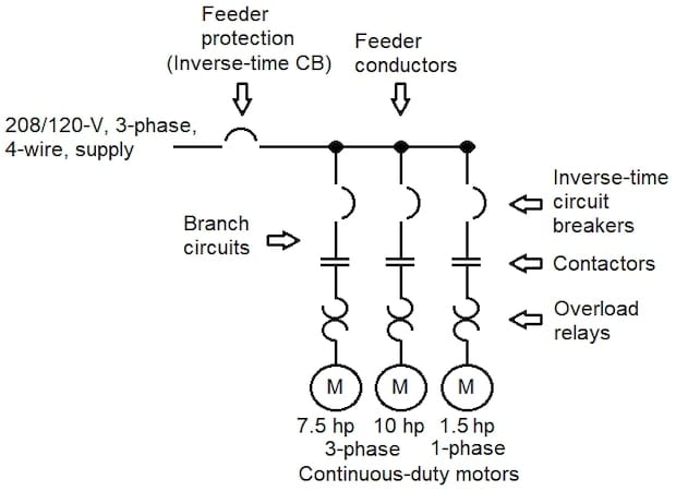
Figure 2. Set-up for Example 2. Image used courtesy of Lorenzo Mari
All units are general-purpose, continuous-duty, squirrel-cage induction motors. Terminals are rated 75°C.
a) Find the motor full-load currents from tables.
b) Find the minimum acceptable feeder conductor ampacity.
c) Find the minimum size of the feeder copper conductors.
d) Find an inverse-time circuit breaker’s maximum rating or setting for the feeder overcurrent protection.
Solution:
a) Enter Table 430.250 and read the following full-load currents under the 200-V column:
10-hp motor = 32.2 A
7.5-hp motor = 25.3 A
Enter Table 430.248 and read the following full-load current under the 115-V column:
1.5-hp motor = 20 A
b) From Section 430.24, the minimum feeder conductor ampacity is:
125% × 32.2 + 25.3 + 20 = 85.55 A
c) Enter Table 310.16, the column of 75°C, copper conductors, and read an ampacity of 100 A for a conductor size N° 3 AWG.
Select copper conductors size N° 3 AWG
d) Find the branch-circuit short-circuit and ground-fault protection using inverse-time circuit breakers for all motors (from Table 430.52(C)(1)):
1. Protect the 10-hp motor at not more than 32.2 A × 250% = 80.5 A. Use a 90-A CB.
2. Protect the 7.5-hp motor at not more than 25.3 A × 250% = 63.25 A. Use a 70-A CB.
3. Protect the 1.5-hp motor at not more than 20 A × 250% = 50 A. Use a 50-A CB.
As covered in Section 430.62(A), the maximum rating or setting for the overcurrent device protecting the feeder must not be greater than:
90 + 25.3 + 20 = 135.3 A
Use a standard ampere rating of 125 A for the motor feeder inverse-time circuit breaker. This nearest rating does not exceed the maximum permitted value of 135.3 A.
Section 430.62(A) rules that the maximum rating or setting for the overcurrent device
protecting a feeder that supplies a group of motors must not be greater than the largest rating or setting of the branch-circuit protective device for any motor plus the sum of the full-load currents of the other motors. This rule applies regardless of whether the group has combinations of single-phase and three-phase motors.
Exception N° 1:
- Suppose one or more instantaneous trip circuit breakers or motor short-circuit protectors protect the motor branch circuits against short circuits and ground faults. In that case, compute the maximum rating of the feeder protective device assuming that each instantaneous trip circuit breaker or motor short-circuit protector is set or rated per Table 430.52(C)(1) for the type of feeder protective device employed.
This exception applies to systems using instantaneous-trip circuit breakers (MCP) or motor short-circuit protectors (MSCP) for branch-circuit protection.
Per sections 430.52(C)(3) and (7), under specific conditions, the rating or setting of these devices may be up to 1300% of the motor full-load current for other than design B energy-efficient and design B premium efficiency motors and as high as 1700% for Design B, energy-efficient and design B premium efficiency motors.
This exception requires the protection of the feeder conductors, basing the rating or setting of the feeder protective device on the assumption that the motor branch-circuit protection uses the same type of device. It means, for example, that if nontime delay fuses protect the feeder, their rating must assume that the motor branch-circuit protection uses the same type of fuses instead of MCPs or MSCPs.
Example 3: Figure 3 shows a 480-V, three-phase, delta-connected, three-wire feeder in an industrial plant feeding two 460-V, three-phase induction motors, as follows:
- 1 x 100-hp squirrel cage
- 1 x 50-hp squirrel cage
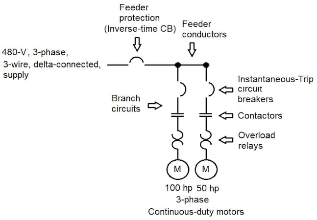
Figure 3. Set-up for Example 3. Image used courtesy of Lorenzo Mari
Both motors use instantaneous-trip circuit breakers to protect the branch circuits against short circuits and ground faults. The 100-hp motor cannot start employing a circuit breaker set at a maximum of 800% of the full-load current, as outlined in Table 430.52(C)(1). Field tests require a rating of 1300% of the full-load current, as permitted in Section 430.52(C)(3).
a) Find the motor full-load currents from tables.
b) Find the minimum acceptable feeder conductor ampacity.
c)Find the minimum size of the feeder copper conductors if terminals are rated 75°C.
d) Find an inverse-time circuit breaker’s maximum rating or setting for the feeder overcurrent protection.
a) Enter Table 430.250 and read the following full-load currents under the 460-V column:
100-hp motor = 124 A
50-hp motor = 65 A
b) From Section 430.24, the minimum feeder conductor ampacity is:
125% × 124 + 65 = 220 A
c) Enter Table 310.16, the column of 75°C, copper conductors, and read an ampacity of 230 A for a conductor size N° 4/0 AWG.
Select copper conductors size N° 4/0 AWG
d) Find the branch-circuit short-circuit and ground-fault protection using instantaneous-trip circuit breakers for both motors (from Table 430.52(C)(1)):
1. Protect the 100-hp motor at not more than 124 A × 800% = 992 A. Use a 1000-A instantaneous-trip circuit breaker.
But it trips at the start.
Then, protect at a maximum of 124 A x 1300% = 1612 A.
Level down to the next smaller size and use a 1600-A instantaneous-trip circuit breaker.
2. Protect the 50-hp motor at not more than 65 A × 800% = 520 A. Use a 600-A instantaneous-trip circuit breaker.
Now, compute the branch-circuit short-circuit and ground-fault protection for the 100-hp motor using an inverse-time circuit breaker.
Protect the 100-hp motor at not more than 124 A × 250% = 310 A. Use a 350-A inverse-time circuit breaker.
As covered in Section 430.62(A), the maximum rating or setting for the overcurrent device protecting the feeder must not be greater than:
350 + 65 = 415 A
Use a standard ampere rating of 400 A for the motor feeder inverse-time circuit breaker. This nearest rating does not exceed the maximum permitted value of 415 A.
Exception N° 2:
Apply the rules in Section 430.94, “Overcurrent Protection,” for a motor control center when the feeder overcurrent protective device also protects it.
The overcurrent protective device’s ampere rating or setting must not exceed the rating of the common power bus of the motor control center.
Section 430.62(B) Other Installations
- You may compute the rating or setting of the feeder overcurrent protective device based on the ampacity of the feeder conductors if this is greater than required by Section 430.24.
This situation is typical in large industrial plants, where feeders may be oversized to accommodate future load growth, changes, or operating conditions requiring the start of several motors simultaneously.
The best practice recommends using the lowest rating or setting as feasible.
NEC Section 430.63 Rating or Setting — Motor and Other Loads
- Where a feeder supplies a motor load plus other load(s), the rating of the feeder overcurrent protection must be not less than the summation of the other load(s) plus the rating permitted in Section 430.52 for a single motor, Section 440.22 for a single hermetic refrigerant motor-compressor, or Section 430.62 for two or more motors.
- Follow Section 430.24 to compute the ampacity for conductors supplying the motor and other load(s).
Example 4: Figure 4 shows the set-up for Example 1 plus a single set of feeder conductors (3 phases and a neutral) supplying a lighting panel. The continuous load on the feeder is 50 A per phase leg, a balanced load.
a) Find the minimum acceptable conductor ampacity for the combined load feeder.
b) Find the minimum size of the copper conductors for the combined load feeder if terminals are rated 75°C.
c) Find an inverse-time circuit breaker’s maximum rating or setting to protect the combined load feeder.
d) Compute a fuse’s minimum standard ampere rating to protect the panel feeder against overcurrent.
e) Compute the minimum ampacity of the panel feeder phase legs.
f) Determine the minimum permitted size of THW aluminum conductors for the panel feeder phase legs.
g) Determine the minimum permitted size of THW aluminum conductor for the panel feeder neutral.
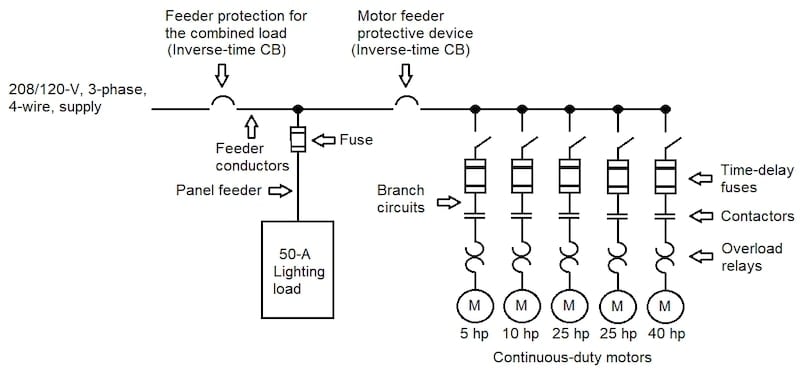
Figure 4. Set-up for Example 4. Image used courtesy of Lorenzo Mari
Solution:
a) From Example 1, the motor load is:
125% × 120 + (2 × 78.2) + 32.2 + 17.5 = 356.1 A
Continuous lighting load (Per Section 430.24): 125% x 50 = 62.5 A
Total load = 356.1 + 62.5 = 418.6 A
Minimum acceptable feeder conductor ampacity = 418.6 A
b) Enter Table 310.16, the column of 75°C, copper conductors, and read an ampacity of 420 A for a conductor size 800 kcmil.
Select copper conductors size 800 kcmil
c) From Example 1, the motor feeder protective device = 400 A
Lighting load: 50 A
Combined load = 400 + 50 = 450 A
Use an inverse-time circuit breaker with a standard ampere rating of 450 A
d) Per Section 215.3, the minimum rating is:
125% x 50 A = 62.5 A
Use a fuse with a standard ampere rating of 70 A
Section 240.4(B) permits using the next higher standard overcurrent device rating.
e) Per Section 215.2(A)(1), the minimum conductor ampacity is:
125% x 50 A = 62.5 A
f) Enter Table 310.16, the column of 75°C, aluminum conductors, and read an ampacity of 65 A for a conductor size N° 4 AWG THW.
Select aluminum conductors size N° 4 AWG THW
The feeder overcurrent device rating is above the phase conductor ampacity. Section 240.4(B) allows this circumstance under certain conditions, all met in this example.
g) Section 220.61(B) contains two considerations that permit using a neutral conductor smaller than the phase conductors. As this example does not qualify for such considerations, use the same conductor as in the phase legs.
Select aluminum conductors size N° 4 AWG THW
Protecting Motor Feeders From Short Circuits and Ground Faults Takeaways
- Compute the rating of a motor feeder short-circuit ground-fault protective device by adding the rating of the largest branch-circuit protective device and the full-load currents of all other motors.
- Size the conductors following Section 430.24.
- Assume that the feeder protective device is the same type as the largest branch-circuit protective device when computing its rating.
- Rate the feeder overcurrent protection as a minimum value, adding the other loads(s) and the rating permitted in sections 430.52, 440.22, or 430.62, depending on the case, when the feeder supplies a motor load and another load (s).