Facebook
 Google
 GitHub
 Linkedin
Protecting Motor Branch Circuits From Short Circuits and Ground Faults
Protecting individual and group motor branch circuits against short circuits and ground faults is essential. Learn how here.
Motor branch circuits need protection from excessive temperatures due to overload, short-circuit, and ground-fault currents. The Informational Note to Section 240.1 states the overcurrent protection for conductors and equipment opens the circuit if the current attains a value that will cause a dangerous temperature in conductors or conductor insulation.
The protection devices do not prevent short circuits or ground faults but protect the motor branch-circuit conductors, the motor control apparatus, and the motors if these faults occur.
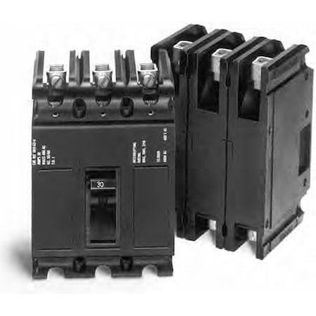
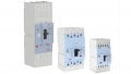
Image used courtesy of EATON
Part IV Motor Branch-Circuit, Short-Circuit, and Ground-Fault Protection
NEC Section 430.51 General
Part IV of Article 430 specifies devices to protect the motor branch-circuit conductors, the motor control apparatus, and the motors against overcurrent due to short circuits or ground faults.
- Part IV applies to motors rated 1 kV or less.
Figure 1 shows an example location for the motor branch-circuit, short-circuit, and ground-fault protection.
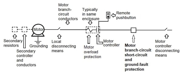
Figure 1. Example location for the motor branch-circuit, short-circuit, and ground-fault protection. Image used courtesy of Lorenzo Mari
Article 100 of the National Electrical Code “Definitions” defines a short circuit as an abnormal connection (including an arc) of relatively low impedance, accidental or intentional, between two or more points having different potentials. This definition is new in the NEC.
Also, Article 100 defines a ground fault as an unintentional conductive connection between an ungrounded conductor and normally non-current-carrying conductors, metal enclosures, metal raceways, metal equipment, or earth.
The NEC emphasizes component protection. Sections 110.9 and 110.10 are significant in this regard:
NEC Section 110.9 Interrupting Rating
- Equipment intended to interrupt fault currents, such as circuit breakers and fuses, must have an interrupting rating that is at least equal to the available fault current at the equipment’s line terminals.
NEC Section 110.10 Circuit Impedance, Short-Circuit Current Ratings, and Other Characteristics
- Select and coordinate the overcurrent protective devices, the equipment short-circuit current ratings, the total impedance, and other circuit characteristics to be protected to clear a fault without extensive damage to the circuit’s electrical equipment.
Protective fuses and circuit breakers open the circuit in response to high currents from short circuits and phase-to-ground faults.
NEC Section 430.52 Rating or Setting for Individual Motor Circuit
Section 430.52(A) General
- Comply with Section 430.52(B) and Sections 430.52(C) or (D) as applicable.
Section 430.52(B) All Motors
- The motor branch-circuit protective device must carry the motor’s starting current.
Section 430.52(C) Rating or Setting
Section 430.52(C)(1) In Accordance with Table 430.52(C)(1)
- Use a protective device with a rating or setting not exceeding the values given in Table 430.52(C)(1) unless otherwise permitted in sections 430.52(C)(1)(a) or (b).
- Per section 430.6(A)(1), compute motor short-circuit and ground-fault protection using the current values in tables 430.247, 248, 249, and 250.
- Do not use the motor nameplate full-load amperes for this purpose.
The percentages of full-load current values in the table below come from the NEC Table 430.52(C)(1).
Summary of NEC Table 430.52(C)(1)
|
Table 430.52(C)(1) Maximum Rating or Setting of Motor Branch-Circuit Short-Circuit and Ground-Fault Protective Devices |
|||
|
|
Percentage of Full-Load Current |
||
|
Type of Motor |
Nontime Delay Fuse |
Time-Delay Fuse |
Inverse Time Breaker |
|
Wound-rotor |
150 |
150 |
150 |
|
DC |
150 |
150 |
150 |
|
Other |
300 |
175 |
250 |
Motors must have a rating or setting of motor branch-circuit short-circuit and ground-fault protective devices capable of carrying the inrush currents at startup. Table 430.52(C)(1) shows the maximum allowable ratings of these devices. You need to know the type of protective device and motor.
A row at the top of the table contains the types of protective devices.
The table has only one row each for the percentages of the full-load current for single-phase and DC (constant voltage) motors.
There are several choices for polyphase motors – like three-phase motors. You need to know whether the motor is wound-rotor, other than wound-rotor, synchronous, squirrel-cage (other than Design B energy-efficient and Design B premium efficiency), or Design B energy-efficient and Design B premium efficiency.
These choices dictate which row to use to find the percentages of the full-load current to calculate maximum overcurrent protection.
Section 430.52(C)(1)(a)
- If the values for the branch-circuit protective devices determined by Table 430.52 (C)(1) do not agree with the standard ampere ratings and settings per Section 240.6, you may use the next higher standard rating or setting.
Example 1: Specify an inverse-time circuit breaker for the 2-hp, 115-V, single-phase motor shown in Figure 2.
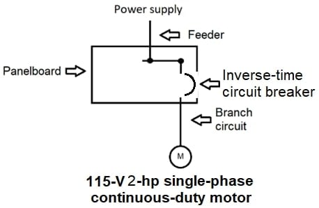
Figure 2. Set up for Example 1. Image used courtesy of Lorenzo Mari
Solution:
Enter Table 430.248 and read full-load current = 24 A for a 2-hp, 115-V, single-phase motor.
Enter Table 430.52(C)(1) and read 250% of the full-load current for a single-phase motor under the inverse-time breaker column.
Multiply the full-load current by 250%.
24 A x 2.5 = 60 A
Select a 60-A inverse-time circuit breaker.
Example 2: Repeat Example 1 for a 3-hp motor.
Solution:
Enter Table 430.248 and read full-load current = 34 A for a 3-hp, 115-V, single-phase motor.
Enter Table 430.52(C)(1) and read 250% of the full-load current for a single-phase motor under the inverse-time breaker column.
Multiply the full-load current by 250%.
34 A x 2.5 = 85 A
Per Table 240.6(A), 85 A is not a standard ampere rating. Section 430.52(C)(1)(a) permits the use of the next higher standard rating which is 90 A.
Select a 90-A inverse-time circuit breaker.
Example 3: Repeat Example 1 for a 5-hp, 230-V, three-phase, wound-rotor motor.
Solution:
Enter Table 430.250 and read full-load current = 15.2 A for a 5-hp, 230-V, three-phase, wound-rotor motor.
Enter Table 430.52(C)(1) and read 150% of the full-load current for a wound-rotor motor under the inverse-time breaker column.
Multiply the full-load current by 150%.
15.2 A x 1.5 = 22.8 A
Per Table 240.6(A), 22.8 A is not a standard ampere rating. Section 430.52(C)(1)(a) permits the use of the next higher standard rating which is 25 A.
Select a 25-A inverse-time circuit breaker.
Example 4: Specify a nontime-delay fuse for a 50-hp, 460-V, three-phase, squirrel-cage motor.
Solution:
Enter Table 430.250 and read full-load current = 65 A for a 50-hp, 460-V, three-phase, squirrel-cage motor.
Enter Table 430.52(C)(1) and read 300% of the full-load current for a squirrel-cage motor under the nontime-delay fuse column.
Multiply the full-load current by 300%.
65 A x 3 = 195 A
Per Table 240.6(A), 195 A is not a standard ampere rating. Section 430.52(C)(1)(a) permits the use of the next higher standard rating, which is 200 A.
Select a 200-A nontime-delay fuse.
Section 430.52(C)(1)(b)
- Apply one of the following practices when the rating specified in Table 430.52(C)(1), or modified per Section 430.52(C)(1)(a), is not sufficient for the motor’s starting current:
- You may increase the rating of a nontime-delay fuse not exceeding 600 A or a time-delay Class CC fuse, but it must not exceed 400% of the full-load current.
- You may increase the rating of a time-delay (dual-element) fuse, but it must not exceed 225% of the full-load current.
- You may increase the rating of an inverse time circuit breaker, but it must not exceed 400% for full-load currents of 100 A or less or 300 % for full-load currents greater than 100 A.
- You may increase the rating of a 601–6000 A fuse classification, but it must not exceed 300% of the full-load current.
Example 5: Specify a time-delay fuse for a 20-hp, 460-V, three-phase, squirrel-cage motor if the rating per Section 430.52(C)(1)(a) is insufficient for the motor startup.
Solution:
Enter Table 430.250 and read full-load current = 27 A for a 20-hp, 460-V, three-phase, squirrel-cage motor.
Enter Table 430.52(C)(1) and read 175% of the full-load current for a squirrel-cage motor under the time-delay fuse column.
Multiply the full-load current by 175%.
27 A x 1.75 = 47.25 A
Per Table 240.6(A), 47.25 A is not a standard ampere rating. Section 430.52(C)(1)(a) permits the use of the next higher standard rating = 50 A.
But 50 A is insufficient to start the motor.
Section 430.52(C)(1)(b) permits an increase in the rating of a time-delay (dual-element) fuse, but it must not exceed 225% of the full-load current.
Multiply the full-load current by 225%.
27 A x 2.25 = 60.75 A. This figure is the maximum allowable rating.
Per Table 240.6(A), 60.75 A is not a standard ampere rating.
Size down to a 60-A time-delay fuse.
NEC Section 430.53 Several Motors or Loads on One Branch Circuit
- Under the conditions specified in sections 430.53(D) and 430.53(A), (B), or (C), two or more motors or one or more motors and other loads may be connected to the same branch circuit.
- The branch-circuit protective devices must be fuses or inverse time circuit breakers.
Although Section 430.52 regulates the rating or setting for individual motor circuits, the NEC recognizes the use of two or more motors or one or more motors and other loads on a single branch circuit.
Section 430.53(A) Not Over 1 HP
- You may connect two or more motors of 1 hp or less to a 120-V branch circuit protected at a maximum of 20 A or a branch circuit of 1 kV or less protected at not over 15 A if complying with all the following conditions:
1. None of the motors has a full-load rating of more than 6 A.
2. Do not exceed any of the ratings of the branch-circuit short-circuit and ground-fault protective devices marked on the motor controllers.
3. The individual overload protection for these motors conforms to Section 430.32.
Section 430.53(B) If Smallest Rated Motor Protected
- You may connect two or more motors or one or more motors and other loads to a branch circuit under all of the following conditions:
1. The branch-circuit protective device is not larger than allowed by Section 430.52 for the smallest rated motor.
2. Each motor has individual overload protection.
3. The branch-circuit protective device won’t open under the most severe normal operating conditions that might be encountered.
Example 6: Figure 3 shows a 480-V, three-phase, three-wire branch circuit in an industrial plant feeding three general-purpose squirrel-cage induction motors.
a.) Which NEC section permits this arrangement using only one 3-pole inverse-time circuit breaker in the panel supplying the load?
b.) Size an inverse-time circuit breaker (a typical thermal-magnetic circuit breaker with a time delay and instantaneous trip characteristic).
c.) Compute the minimum ampacity required for the branch-circuit conductors.
d.) Determine the minimum size of the branch-circuit copper conductors if terminals are rated 75°C.

Figure 3. Set up for Example 6. Image used courtesy of Lorenzo Mari
Answer:
a.) Section 430.53(B) permits this arrangement under several conditions.
The rule’s basic approach is that the branch-circuit protective device must not exceed the rating allowed by Section 430.52 for the 1-hp motor. Additionally, each motor must have a separate overload protection, and the circuit breaker must not open under the most severe normal conditions of service.
In this example, the motor starter for each of the three motors must provide overload protection.
b.) Use the motor full-load currents in Table 430-250 to calculate the maximum permitted rating or setting of the branch-circuit protective device. These values are:
1-hp motor = 2.1 A
1.5-hp motor = 3 A
5-hp motor = 7.6 A
Select the maximum branch-circuit inverse-time circuit breaker rating per Table 430.52(C)(1), based on the 1-hp motor.
250% x 2.1 A = 5.25 A
Table 240.6(A) shows that 5.25 A is not a standard ampere rating. Section 430.52(C)(1)(a) permits the use of the next higher standard rating which is 10 A.
The new Table 240.6, in the 2023 NEC edition, includes a standard ampere rating of 10 A for fuses and inverse-time circuit breakers. In previous NEC editions, the lowest standard ampere rating for these devices was 15 A.
Section 430.52(C)(1)(a) does not restrict the use of a 10-A protective device.
Section 210.23(A)(2), “Loads not permitted for 10-A branch circuits,” does not include motor branch circuits on the list – it only contains receptacles, appliances, garage door openers, and laundry equipment.
The total full-load current of the simultaneous operation of the three motors is
2.1 A + 3 A + 7.6 A = 12.7 A
12.7 A is larger than 10 A. The circuit breaker will trip, and starting the 5-hp motor with the other two motors running is impossible.
We cannot select 15 A, the next standard rating for a circuit breaker after 10 A, because this is not the “next higher standard rating or setting” after 5.25 A in Table 240.6(A).
We can refer to Section 430.52(C)(1)(b), which allows an increase in the rating of an inverse time circuit breaker when the rating modified per Section 430.52(C)(1)(a) is not enough for the starting current of the motor. But Section 430.52(C)(1)(b)(3) does not permit to exceed 400% for full-load currents of 100 A or less.
400% x 2.1 A = 8.4 A
The 15-A circuit breaker exceeds the 400% limit and is unsuitable.
In conclusion, the arrangement in Figure 3 is not feasible using a 10-A inverse-time circuit breaker, and it would be an NEC violation to choose 15 A.
But let’s have a further discussion.
Section 210.23(A)(1), “Loads permitted for 10-A branch circuits,” permits only lighting loads, exhaust fans in dwellings, and gas fireplace units supplied by individual branch circuits.
Since Section 210.23(A)(1) appears to intend to supply only branch circuits with low loads, such as lights, not industrial motors, we can deduce that protective devices for industrial motor branch circuits may start at a rating of 15 A.
Let’s repeat the exercise using a 15-A circuit breaker if such is the case.
The total full-load current of the three motors operating simultaneously (12.7 A) is within a circuit breaker’s rating of 15 A. Additionally, we can accommodate the starting inrush current of the 5-hp motor into the circuit breaker’s time delay so that it can start with the other two motors running, which is “the most severe normal operating conditions that might be encountered.”
Then, use a 15-A inverse-time circuit breaker.
c.) The minimum ampacity of the branch-circuit conductors, per Section 430.24, is
125% x 7.6 + 2.1 + 3 = 14.6 A
d.) Per Table 310.16, the minimum size of the branch-circuit copper conductors is N° 14 AWG with an ampacity of 20 A (75°C rating).
Protecting Motor Branch Circuits Takeaways
- Motor circuit protection safeguards conductors supplying power to the motor, the motor control apparatus, and the motors against overcurrent caused by short circuits or ground faults.
- Section 430.52 contains the rules to compute the maximum size or setting of the overcurrent device protecting an individual motor branch circuit.
- Table 430.52(C)(1) lists the percentages of full-load current for several types of protective devices.
- To size the protection devices, use the full-load current values in tables 430.247 through 430.250. Do not use nameplate values.
- Section 450.52(C)(1)(a) allows increasing the size of the overcurrent device if the calculated size does not correspond to a standard ampere rating per Section 240.6.
- Section 450.52(C)(1)(b) permits increasing the size of the overcurrent device even more if the motor is unable to start.
- The new Table 240.6(A) includes a 10-A rating as a standard overcurrent protective device.
- While Section 430.52 provides specific regulations for sizing the branch-circuit overcurrent device for an individual motor circuit, Section 430.53 acknowledges using multiple motors or loads on a single branch circuit.