Facebook
 Google
 GitHub
 Linkedin
Stepper Motors Part 2: Motor Drive Circuit Types and Operation
This article reviews the types and operation of stepper motor drive circuits used in precise positioning and control applications. It examines full-step, half-step, and micro-stepping drive circuits and their functions, working principles, and control mechanisms.
To catch up on this series, please follow these links:
Stepper Motors Part 1: An Overview
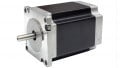
A stepper motor delivers rotary motion in high-precision applications by rotating in small precise increments. These motors require a control circuit known as a motor drive circuit to control the voltage and current delivered in the motor windings to control the speed and position of the rotation. This article will focus on stepper motor drive circuits and how they operate in various applications.
Stepper Motor Drive Circuits
There are different types of stepper motor drive circuits which include:
Full-Step Drive Circuit
Full-step drive circuits are the simplest type of stepper motor drive circuit. They offer a full-step current to the windings of the stepper motor, leading to a movement of one step per electrical pulse. This drive mostly alternates the current direction to the two phases of the stepper motor.
This type of drive circuit comprises four switches for each winding. The switches can be solid-state devices such as bi-polar transistors or MOSFETs, or mechanical relays. Switches are configured in bridge arrangements having two switches on every side of the motor windings.

Figure 1. Logic table for full-step operation. Image used courtesy of Bob Odhiambo
For the motor to rotate, the switches are turned off and on in a specific sequence, as shown in Figure 1. To rotate the motor, the switches can be configured in the following switching for motor phase A.
Switch 1 and 4 are on while 3 and 2 are off, allowing current to flow in only the first and the fourth motor winding of phase A, thereby generating a magnetic field that pulls the rotor towards that side.
In a directional change switch, 2 and 3 are turned on while 1 and 4 are turned off to allow current to only flow through 2 and 3, generating a magnetic field that pulls the rotor to the other side.
The same process occurs in phase B with the step sequence shown in Figure 1. The process repeats itself for a continuous rotating motion of the motor.
A full-step drive produces the highest torque with minimum vibration, but the limitation of this component is that it provides the lowest resolution of all the drive circuits. In full-step operation mode, phases A and B of the motor are activated simultaneously, thereby providing an attractive force relative to the wave drive while keeping the resolution of the wave drive method constant. Every step in the full-step sequence rotates the motor in a defined angular distance.
Half-Step Drive Circuit
The half-step drive circuit gives out the intermediate resolution by using a micro-stepping way that alternates the current direction to the two phases and center tap of the stepper motor. The outcome of all these is more accuracy in positioning.
This type of stepper motor drive operates the stepper motor to rotate in half-step increments. Such a drive is often used in areas requiring precision control over the motor speed and position.
The half-step drive circuit uses transistors to control the current flowing in the motor windings. A pair of transistors for each winding switch the current off or on. The switching is controlled by a control circuitry or microcontroller that sends pulses to drive the motor.

Figure 2. Motor coil sequence for the half-step drive circuit. Image used courtesy of Texas Instruments
The half-step drive circuit is divided into two stages; the half-stepping and the full-stepping. As shown in Figure 2 above, step 3 is the full step of the coil sequence, while step 2 is half the full step.
During the half-stepping stage, the motor rotates half a step for every pulse received from the drive circuit, as seen in step 2, Figure 2. In this process, first, one winding is energized at a time and then simultaneously energized, repeating in reverse order. This sequence results in a half-step rotation in one direction, then rotation to its original position and, finally, in a half-step to the other side.
Micro-Stepping Drive Circuit
A micro-stepping motor drive circuit controls the motor using small increments for precision. This fine level of control is achieved by gradually controlling the current flowing through the motor windings. The current control uses an advanced algorithm to drive the motor with a sinusoidal waveform other than a simple square wave, as in simple drives. The sinusoidal waveforms are generated by a microcontroller to adjust the speed and position of the motor. The generated waveform is sent as a signal to the drive.
The drive’s main advantage is the precise increment of motor motion control. However, some issues arise with micro-step drives known as slow decay. Slow decay is a phenomenon in which the current flowing in motor windings is slow to decay with the changes in drive signals. This, in turn, causes the motor to lose its torque or even miss some steps. Various factors lead to slow decay, such as resistance and inductance of the motor winding. To mitigate this issue, active current regulation controls the initial winding to ensure quick and smooth delay.

Figure 3. Shows how slow and mixed decay interacts in both phases of the stepper motor with steps input in an 8-micro-step operation cycle. Image used courtesy of Bob Odhiambo
Another method of addressing slow decay is mixed decay. This method combines fast decay and slow decay for optimal motor performance. The current in the motor winding decays quickly with a change in the direction of the drive signal. The current is held at a lower level for a short period to improve the motor’s holding torque.
Takeaways of Stepper Motor Circuits
Below are some key points to note from the article.
- Stepper motor drive circuits are circuits used to control the stepper motor's precise positioning and speed of rotation.
- The types of stepper motor drive circuits include; half-step drives, full-step drives, and micro-stepping drives.
- Full-step drive gives an output of a full-step current to move a stepper motor one step per electrical pulse.
- Mixed and slow decay are distinct ways to control current decay in stepper motor drives.
Featured image used courtesy of Adobe Stock