Facebook
 Google
 GitHub
 Linkedin
Troubleshooting Electric Motor Power Circuits
The two major parts of a motor circuit are the motor power circuit and the motor control circuit. Learn some basic troubleshooting tips for these kinds of motor circuits.
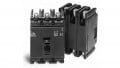
A motor power circuit is the section of an electrical motor circuit that delivers high voltage or current to an electric motor. A motor power circuit includes a disconnect switch, a control transformer, protective devices (fuses or circuit breakers), a motor starter, and a motor (See Figure 1).
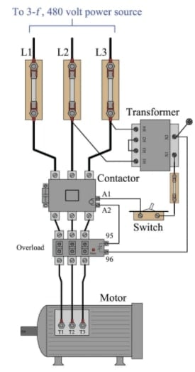
Figure 1. A motor power circuit includes a disconnect switch, a control transformer, overload protection devices, a motor starter, and a motor.
An electric motor can be DC, single-phase AC, or three-phase AC. Incoming power lines must have a mechanism to switch off, lockout, and tagout the circuit power. They must also include fuses or circuit breakers sized to protect the system. A motor can be controlled by a magnetic motor starter or a motor drive.
A motor starter includes devices that are used in the motor power circuit, such as normally open (NO) power contacts and motor overload current monitoring. A motor starter also includes devices that are used in the motor control circuit, such as NO or normally closed (NC) auxiliary contacts, a starter coil or circuit, and NC overload contacts. A magnetic motor starter is a contactor that includes an overload section. Contactors can be used to control single-phase motors that have built-in overload protection. Motor power circuits are classified into different sections for the purpose of troubleshooting.
Disconnect Switches
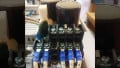
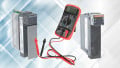
A disconnect switch, also known as a disconnect, is a switch that disconnects the supply of electric power from electrically powered devices such as motors and machines. Disconnects are used to manually remove power from or apply power to a circuit. The disconnect switch connects the load to the building power distribution system (see Figure 2).
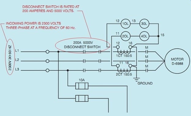
Figure 2. The disconnect switch connects the load to the building power distribution system. Image courtesy of Industrial Electronics
Disconnect switches include overcurrent protection to protect the load and system from short circuits, faulty ground connections, and excessive current levels. An overcurrent protection device (OCPD) is a fuse or circuit breaker that blocks the flow of current when the amount of current exceeds the design load. A disconnect switch can be used to switch off, lockout, and tagout a load or energized equipment during system maintenance. A disconnect switch enclosure is typically the starting point for troubleshooting a load or energized equipment because it contains fuses and circuit breakers.
Power Circuit Terminal Identification
In a motor power circuit, the terminals and conductors can be identified with different markings depending on the equipment manufacturer and equipment installer. For example, three-phase power lines may be marked as L1, L2, and L3 or R, S, and T. Three-phase motor terminals may be marked T1, T2, and T3 or U, V, and W. Single-phase power lines may be marked L1 and N for 120 VAC circuits or L1 and L2 for 240 VAC circuits. Single-phase motor terminals may be marked T1 and T2 or with specific manufacturer numbers, such as 1 and 2. Single-phase motor terminals may also be marked with different colors, such as blue or black for T1 and white for T2.
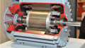
DC power lines are normally marked DC+ and DC–. DC motor armature windings are normally marked A1+ and A2–. DC series motor series windings are normally marked S1 and S2. DC shunt motor shunt windings are normally marked F1 and F2. DC compound motors have an armature, series field, and shunt field (see Figure 3).
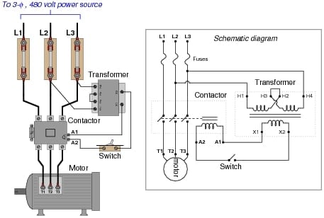
Figure 3. In a motor power circuit, the terminals and conductors can be identified with different markings depending on the equipment manufacturer and equipment installer.
Troubleshooting Motor Power Circuits
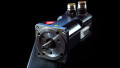
Troubleshooting is the systematic elimination of the various parts of a system to find a malfunctioning element. When performing troubleshooting tasks, the different parts of a circuit within an electrical system are categorized into sections to aid in determining where to begin the troubleshooting process. For example, an HVAC system can be categorized into a power circuit, control circuit, and interface connecting the power circuit to the control circuit. (See Figure 4).
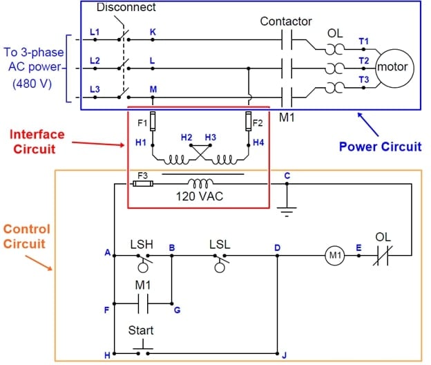
Figure 4. To aid in troubleshooting tasks, the different parts of a circuit within an electrical system are categorized into sections, such as the power circuit, control circuit, and interface connecting the power circuit to the control circuit.
The power circuit is the high-voltage section of the circuit that includes the incoming power supply, fuses or circuit breakers, motor starter contacts, and motor. In an HVAC circuit, the original equipment manufacturer (OEM) can provide the across-the-line starting circuit. The across-the-line starting circuit is used when the initial inrush current of the compressor motor does not cause a problem, such as a greater than 5% drop in the main voltage supply, when starting.
The control circuit controls the motor starter coils in the power circuit. The control circuit normally operates at a lower voltage than the power circuit. A step-down transformer is an interface used to reduce the voltage from the power circuit to the control circuit.
When troubleshooting a power circuit, electrical measurements are taken with the appropriate test instruments, such as a DMM. Voltage measurements are the first measurements taken to indicate if power is present. Current measurements must also be taken and compared to nameplate ratings to determine motor loading.
The first voltage measurement taken is the power circuit voltage at the fuses or circuit breakers. Before taking any measurements, it should be ensured that proper PPE is worn, plant and safety procedures are followed, and that the DMM is checked for proper operating condition before and after the voltage measurements.
When troubleshooting, an electrical print is used as a reference to help identify the components and devices used in a circuit and how they are connected to other components and devices. However, an electrical print does not identify the actual location of the components and devices in the wired panel. The print component layout can be different from the actual component layout.
Troubleshooting the power circuit begins by taking a measurement of the incoming voltage level to verify that the voltage is within +5% to –10% of the equipment voltage rating. Fuses and circuit breakers are also tested for proper operation by taking voltage measurements in and out of each fuse or circuit breaker. A properly operating fuse or circuit breaker must have the same voltage coming out as going in. The voltage in and out of the control transformer must also be tested.
When a motor is running, both voltage and current measurements should be taken. The voltage must be within the +5% to –10% range, and the current should not exceed the motor maximum-rated current as listed on the motor nameplate.
Related Content