Facebook
 Google
 GitHub
 Linkedin
Primary Distribution Systems—Part 3: Overhead and Underground Choices
Overhead vs. underground power distribution: Learn the cost, reliability, and design trade-offs for medium voltage power systems across urban, suburban, and rural territories.
Primary distribution systems deliver medium-voltage power—typically in the 4 to 35 kV range—from substations to local transformers and switching points. The core objective is to move energy reliably at the lowest practical cost while meeting safety and performance standards. In practice, that task involves a set of engineering decisions with long-term financial and operational consequences. Among the most consequential is whether to build overhead or underground.
Each approach brings distinct construction methods, protection practices, cost structures, and reliability profiles. This article reviews both configurations in detail and then examines the economic and reliability trade-offs that guide deployment across dense urban cores, suburbs, and rural territories.
Overhead Distribution Systems
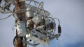
Overhead feeders remain the dominant approach across much of North America because hardware is straightforward to install, inspect, and modify. Typical construction includes wood, steel, or concrete poles; crossarms for phase spacing; polymer or porcelain insulators; and aluminum conductors such as ACSR or AAAC strung at clearances set by code and local conditions.
Protection and control equipment—fuses on laterals, reclosers on mains, sectionalizers, and line regulators—are mounted on poles to sectionalize faults and manage voltage. Capacitor banks provide reactive support and power-factor correction, and distribution automation devices communicate switching states to control centers. In dense areas, compact construction with vertical phase arrangements may be favored; in rural spans, longer pole spacing and larger conductor sags are common to reduce structure count.
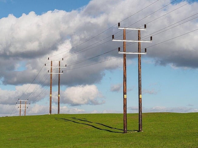
Figure 1. Overhead power distribution lines. Image used courtesy of Wikimedia.
Pole-Mounted Equipment
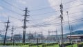
Pole tops typically host reclosers and switches to isolate sections rapidly during faults and to enable backfeeding from alternate sources. Voltage regulators (single- or three-phase) keep service within ANSI voltage limits as load and feeder length vary. Capacitors are mounted mid-feeder or near load pockets to reduce current and losses.
Single- and three-phase transformers hang near loads; where larger blocks of load exist, three-phase banks on dedicated poles or pad mounts may be used instead. Modern reclosers integrate microprocessor relays, enabling curve coordination, SCADA visibility, and distribution fault location features to shrink patrol time.
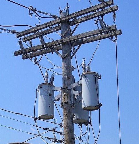
Figure 2. Pole-mounted three single-phase distribution transformers. Image used courtesy of Wikimedia.
Advantages
Lower capital cost: Erecting poles and stringing conductors is typically several times less expensive than building equivalent underground circuits. Edison Electric Institute (EEI) analyses have long shown that new underground distribution construction can cost five to ten times comparable overhead installations, depending on terrain and urban constraints.
Easier fault detection and repair: Visual inspection often spots broken conductors, insulator flashover, or downed limbs. Sectionalizing with visible switches allows quick isolation, and line crews can access equipment without excavation. As a result, restoration logistics are often more straightforward on overhead feeders than on buried ones.
Disadvantages
Weather exposure: Storms, wind, ice, and airborne debris directly impact overhead plant. Florida Power & Light’s post-hurricane assessments identified trees and wind-blown debris contacting conductors as a leading outage driver during major storms, leading to hardening and targeted undergrounding.
Vegetation-related faults: Even with routine trimming, tree growth and falling branches contribute significantly to sustained and momentary interruptions during normal operations and especially during severe weather. Targeted hardening—covered conductor, spacer cable, or selective undergrounding—can reduce this exposure but at added cost.
Underground Distribution Systems
Cable Types
Cross-linked polyethylene (XLPE) is the dominant modern medium-voltage distribution cable insulation. XLPE offers strong dielectric performance, higher temperature ratings than legacy paper systems, and dry design without oil. Extruded XLPE and EPR families have become the standard for new distribution and sub-transmission builds worldwide.
Paper-insulated, lead-covered (PILC) cables remain in older urban networks. While robust, PILC requires oil or impregnating compound management, is heavier, and demands specialized splicing expertise; many utilities replace PILC during major rebuilds with XLPE to reduce maintenance and simplify accessories.
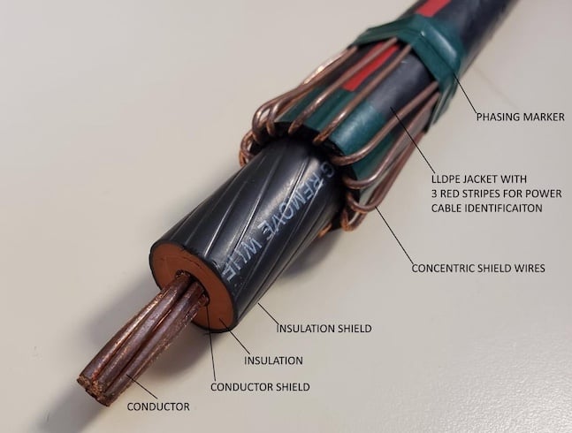
Figure 3. Cross-section of typical 15 kV #2 copper medium-voltage EPR cable. Image used courtesy of Wikipedia.
Pad-Mounted Transformers and Switchgear
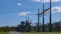
Underground feeders commonly terminate in pad-mounted, tamper-resistant enclosures. Single- and three-phase pad-mounted transformers in dead-front configurations accept loadbreak elbows for safe isolation and switching with a hotstick. Loop-feed arrangements allow sectionalizing and backfeeding between two sources, improving service continuity.
Where additional flexibility is required—especially for commercial corridors or dense residential blocks—pad-mounted switchgear or compact ring main units provide multiple ways to tie, sectionalize, and protect laterals. Fault indicators, either in elbows or on cable sections, support rapid patrol after a fault trip.
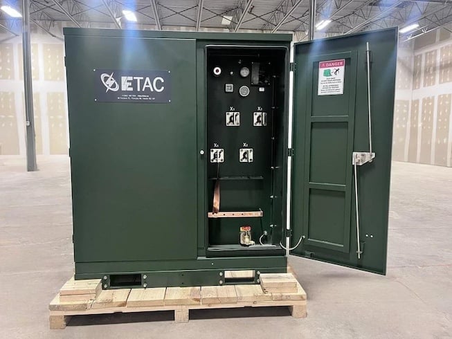
Figure 4. Pad-mounted distribution transformer. Image used courtesy of Wikipedia.
Advantages
Improved reliability in severe weather: Buried conductors are shielded from wind, ice, and falling trees, so storm-related outage frequency often drops on undergrounded segments. Programs such as Washington, DC’s DC PLUG initiative target the worst-performing overhead feeders and report large expected reductions in storm-related interruptions on selected segments when converted to underground.
Better aesthetics and land use: Urban stakeholders often prefer the absence of poles and overhead conductors along streetscapes. Planning documents from regulators frequently cite visual benefits and roadway clearances among reasons to consider undergrounding in redevelopment corridors.
Disadvantages
Higher installation cost: In constrained urban corridors, trenching, duct banks, manholes, traffic control, and restoration work drive costs significantly higher than overhead construction. The California Public Utilities Commission cites an average of roughly $3.8 million per circuit-mile to convert overhead distribution to underground across the state’s largest investor-owned utilities—figures that vary with soil, roadway conditions, and utility congestion.
More complex fault detection and repair: Faults are not visible, and locating the failure requires test equipment (such as time-domain reflectometry, thumping, and acoustic pinpointing) followed by excavation or manhole entry. In flood-prone or corrosive environments, accessories may demand additional attention, and restoration can take longer than stringing a new overhead span or replacing a pole-top transformer.
Economic and Reliability Trade-offs
Urban Vs. Rural Deployment Decisions
Customer density significantly influences cost per served customer. EEI’s distribution planning work assumes on the order of a few dozen customers per mile for many investor-owned utility (IOU) territories. At the same time, rural electric cooperatives average roughly seven consumers per mile of line—far fewer revenue meters to share fixed costs, which challenges the economics of capital-intensive undergrounding at scale in remote areas.
In a dense downtown, underground feeders offer clear advantages: reduced visual impact, fewer conflicts with cranes and high-profile vehicles, and better storm performance. In suburban greenfield subdivisions, developers often favor undergrounding to meet planning requirements and aesthetics while trenching is already underway for water, sewer, and communications.
In sparse rural corridors with long spans per customer, overhead lines remain the most cost-effective option, supplemented by vegetation management, selective reconductoring, and covered conductors in wildfire or heavy-vegetation zones. For example, Southern California Edison has pursued widespread covered-conductor deployment for wildfire mitigation at a fraction of the per-mile cost of undergrounding.
Life-Cycle Cost Comparisons
A credible comparison weighs the total cost of ownership over decades:
Capital expenditures: Duct bank excavation, encasement, manholes, cable, splices, terminations, and pad-mounted equipment drive underground CapEx. Conversion of existing overhead corridors is especially costly in built environments. Regulators in California estimate about $3.8 million per circuit-mile for conversion projects, though actuals vary widely. Overhead new-build costs are generally an order of magnitude lower, depending on terrain and span lengths. EEI’s multi-utility analyses have consistently found underground to be several times the cost of overhead for new construction and conversion.
Operations and maintenance: Underground installations avoid routine vegetation clearing and have fewer exposure-driven faults, often reducing O&M variability. Some empirical analyses find lower O&M and improved outage durations on undergrounded sections when other variables are held constant, though results are sensitive to local soils, groundwater, and construction quality.
Reliability impact and outage costs: Utility reliability metrics help quantify benefits. According to the U.S. Energy Information Administration’s reliability table, national SAIDI in 2024 measured 662.6 minutes per customer including major event days (MEDs), versus 131.6 minutes excluding MEDs—illustrating the heavy influence of storms. Reducing storm exposure through targeted undergrounding on the worst-performing feeders can significantly reduce the all-events component.
Restoration logistics and risk: While underground segments may experience fewer faults, time to locate and repair a failed cable or splice can exceed overhead restoration when access requires excavation or manhole work, particularly in congested streets. Many utilities therefore combine undergrounding with feeder automation, loop schemes, and remote switching to confine outages to the smallest possible section, regardless of construction type.
Alternatives and intermediate hardening: Where undergrounding costs are prohibitive, covered conductor, spacer cable, stronger poles, improved guying, and targeted recloser placement can capture a portion of the reliability benefit. A recent review of wildfire-mitigation investments in Southern California reported covered-conductor installations on the order of hundreds of thousands of dollars per mile, compared with several million dollars for undergrounding—illustrating a distinct middle path in high-risk corridors.
Impact on Outage Frequency and Restoration Time
A practical way to frame reliability trade-offs is to segment by cause:
Weather- and vegetation-driven outages: Overhead is vulnerable to trees, wind, and ice; underground is largely insulated from these causes. Targeted undergrounding programs in storm-prone regions, such as DC PLUG and Florida’s Storm Secure Underground Program, explicitly pursue the feeders with the worst storm history and constrained vegetation corridors, reporting substantial expected improvements on those segments.
Equipment- and third-party-driven outages: Excavation damage, cable defects, and accessory failures dominate for underground; vehicle strikes and conductor/insulator failures are common on overhead. Remote switching, fault indicators, and feeder reconfiguration shorten the customer-hours lost for both approaches.
Restoration performance: Nationally, the difference between all-events and non-MED reliability highlights storm exposure. EIA’s 2024 data shows SAIFI of 1.531 interruptions per customer including MEDs versus 1.065 without MEDs. System designs that reduce storm susceptibility—whether via undergrounding, covered conductor, or sectionalized tie points—thus pay off especially during extreme weather.
Community and road impacts: Underground restorations may require lane closures, excavation, and longer construction windows, which factor into social cost-benefit assessments for urban corridors. Overhead restorations often proceed with traffic control but can be quicker to complete for single-structure replacements, barring access constraints in alleys or constrained sidewalks.
A Balancing Act
Primary distribution design is a balancing act among cost, reliability, safety, and community expectations. Overhead construction delivers low upfront cost, easy access, and rapid restoration but remains susceptible to storms and vegetation. Underground construction reduces storm exposure, improves streetscapes, and supports looped topology at the expense of higher capital cost and more complex fault location and repair.
Modern distribution planning often lands on a targeted mix: keep overhead where it is cost-effective and relatively reliable; apply covered conductor or other hardening where wildfire or vegetation risk is high; and underground selectively in dense corridors and on the worst-performing feeders. Recent reliability data from EIA highlight how major events drive national interruption minutes, while utility programs in Washington, DC and Florida show how selective undergrounding can materially reduce storm-driven outages on targeted segments.
The most resilient networks result when construction method, protection strategy, and automation are matched to local risk and customer density—achieving a robust service profile at a sustainable life-cycle cost.