Facebook
 Google
 GitHub
 Linkedin
Probe Capacitance, Ground Inductance Effects in HV Measurements
High-voltage probing errors scale with voltage and dV/dt, as probe capacitance and ground inductance inject energy, distort waveforms, and stress insulation.
Measuring high-voltage systems is different from testing low-voltage or digital signals. When working with voltages above 1 kV, especially in fast-switching power systems, the measurement process can affect the circuit. Oscilloscope probes can change circuit behavior, lower measurement accuracy, and impact safety.
At low frequencies, measurement errors are usually due to bandwidth limits. During high-voltage probing, errors depend on both the voltage and charging speed. Probe capacitance that is negligible at 5 V can store notable energy and act as a current source at kilovolt levels. Ground inductance, which may cause only small oscillations at low voltages, can create large voltage spikes when high transient currents are present in high-voltage switching.
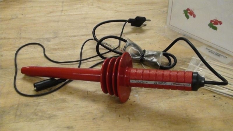
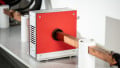
Figure 1. A well-insulated high-voltage probe rated at 40 kV. Image used courtesy of Wikimedia Commons
Modern power systems usually experience voltage changes of tens of kilovolts per second. Devices such as high-power IGBTs can reach dV/dt values over 20-100 kV/µs. Even small probe capacitances can cause transient currents in the ampere range.
These currents can distort measured waveforms and flow into sensitive control circuits, isolation components, or the ground of the measurement equipment, sometimes causing effects that look like circuit faults. In high-voltage systems, probe capacitance (Cp) and ground inductance (Lg) are energy paths that affect system characteristics, not just minor parts of the measurement setup.
High-Voltage Probe as a Capacitive Divider
High-voltage probes use built-in capacitance, not just resistors, to lower the voltage. Most HV probes form a capacitance divider between the high-voltage point and the measurement device, safely reducing the voltage before it reaches the oscilloscope. This approach works for large voltages and wide bandwidth, but it also means the probe’s capacitance becomes an important part of the system under test.
In a simple model, the measured voltage depends on the capacitance divider formed by the probe capacitance (Cp) and the circuit’s effective capacitance to ground (Cc). The oscilloscope does not measure the full high voltage directly. Instead, it measures the voltage that appears across this divider, as shown in the following expression:
$$V_{meas} = V_{HV} \times \frac{C_c}{C_c + C_p}$$
The equation shows that the measured voltage (Vmeas) depends on the capacitors’ ratio, not just the voltage itself. In many high-voltage systems, the circuit’s capacitance to ground is not well defined and can change with layout, nearby conductors, insulation shape, or even humidity. As a result, poorly controlled probe capacitance can change the divider ratio and cause measurement errors.
In practice, changing or replacing a probe, using a longer cable, or moving the probe can change the voltage scaling you observe. This is especially important in floating or weakly grounded high-voltage circuits, where the circuit’s capacitance to ground can be similar to the probe’s capacitance. In these cases, the probe not only measures voltage but also affects the voltage division, making it difficult to obtain consistent and accurate readings, unless you carefully control the probe and circuit setup.
Energy Injection Due to Probe Capacitance
Probe capacitance does more than scale voltage. It also stores energy when connected to a high-voltage node. At low voltages, the energy in a few picofarads is very small, but at kilovolt levels, this stored energy can be large enough to affect circuit operation and insulation reliability. The energy stored in the probe capacitance is given by:
$$E = \frac{1}{2} C_p V^2$$
The quadratic relationship with voltage is important because doubling the voltage increases the stored energy by four times. This means probe effects can grow quickly as voltage rises. For example, a 10 pF probe capacitance at a 5 kV node stores about 125 µJ of energy. While this amount seems small, it can be significant in systems with high-speed gate drivers, sensitive isolation, or local electric field stress.
In high-voltage gate driver circuits, quickly charging and discharging stored energy during switching can send transient currents into the control circuits. This can disrupt gate voltage levels and may cause false turn-on or unstable switching.
In insulation systems, especially those with voids, sharp edges, or damaged material, a sudden release of energy from the probe capacitance can locally increase the electric field and raise the risk of partial discharge.
These effects show an important point in high-voltage measurement: probe capacitance does more than just load the circuit; it also exchanges energy with it. In fast-switching high-voltage systems, this energy exchange can distort waveforms, reduce measurement accuracy, and, in some cases, add stress to insulation or cause early failure.
Probe Capacitance Effects in High-Voltage Systems
One effect of probe capacitance in high-voltage systems is increased displacement current during fast switching. In this case, probe capacitance acts as a direct path for displacement current as the voltage changes. Unlike conductive current, which flows through resistors, displacement current flows through capacitance and depends on how quickly the voltage changes. Even a small probe capacitance can create a large transient current during high dV/dt conditions, as shown in the following equation:
$$i_c = C_p(\frac{dV}{dt})$$
The displacement current is directly proportional to both the probe capacitance and the rate of voltage. For example, a 10 pF probe connected to a node switching at 50 kV per microsecond can create a transient current of about 0.5 amps. This current appears briefly during each switching event as a sharp pulse that injects charge into the circuit and the measurement return path. Figure 2 shows that even a 10 pF probe can produce transient currents close to 0.5 A at dV/dt values typical of modern high-voltage SiC converters.
These transient currents can cause engineering problems. The displacement current through the probe can temporarily shift the gate-emitter or gate-source voltage, which may lead to false triggering, unintended turn-on, or higher switching losses. In isolated systems, this current may pass through isolation barriers, opto-isolators, or transformers, putting extra stress on them and speeding up insulation breakdown.
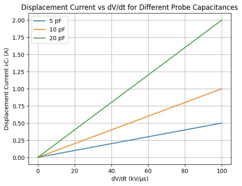
Figure 2. Illustration of displacement current through probe capacitance versus voltage slew rate (dV/dt), showing how even small capacitances can generate large transient currents in high-voltage, fast-switching systems. Image used courtesy of Bob Odhiambo
Another effect of capacitance in high-voltage systems is insulation stress caused by measurement. Probe capacitance can unintentionally couple high-voltage transients into low-voltage parts of the system, acting as a path for voltage spikes. Through the probe’s capacitance, rapid voltage changes can reach the oscilloscope ground, nearby low-voltage components, and cable shielding. This can increase local electric fields and introduce common-mode disturbances that were not part of the original circuit design, possibly compromising insulation integrity.
In high-voltage systems, insulation reliability depends on well-defined creepage and clearance distances, which prevent surface arcing and air breakdown under certain voltage and environmental conditions. When probe-induced transients couple into nearby conductors and grounded parts, the voltage stress across these insulation paths can rise unexpectedly. This increases the risk of insulation failure in compact designs where creepage and clearance are already close to their limits, reducing safety margins.
During testing and debugging, measurement-induced stress is a concern because the temporary probing setup may exceed the insulation limits assumed in the final design. In severe cases, capacitive coupling from the probe can cause surface discharges, internal partial discharges, or localized heating, all of which reduce insulation reliability. For this reason, in a high-voltage system, probing should be considered as a possible source of insulation stress, not just a passive diagnostic step.
Ground Inductance Effects Under High Voltage
When measuring high-voltage power, ground inductance is often a main source of waveform distortion. The oscilloscope ground lead is not a perfect reference path. During rapid switching, it acts like an inductor and can produce significant voltage across it when transient current flows.
Long probe ground leads create a large loop area and add inductance to the return path. When fast transient current flows, this inductance causes an unwanted voltage drop, as shown by the equation below. Even a few amps of displacement current can create hundreds of volts across a small ground inductance, making the oscilloscope show overshoot or ringing that does not reflect the real circuit but comes from the measurement loop.
$$V_L = L_g(\frac{di}{dt})$$
When ground inductance combines with probe capacitance, they form an unintended LC resonant circuit that produces ringing or exaggerated overshoots. Because of this ringing, switching waveforms can look more severe than they really are, which can lead to incorrect conclusions about device stress, insulation margins, or EMI performance.
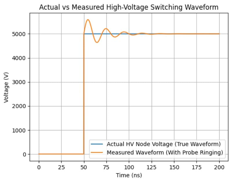
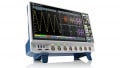
Figure 3. Comparison of the actual high-voltage switching waveform and the oscilloscope’s measured signal showing how probe ground inductance and capacitance can introduce ringing and false overshoot. Image used courtesy of Bob Odhiambo
Safety and Instrumentation Risk Considerations
High voltage probing is not just about waveform accuracy; it is also a major safety concern. In HV systems, probe capacitance and ground inductance can create unintended current paths, raise ground potentials, and introduce electrical stress that affects both insulation and instrumentation.
Since the bench oscilloscope is earth-grounded, its probe ground clips are tied to earth. In floating high-voltage circuits, probe capacitance can couple fast transients into the scope ground, referencing the HV domain to earth and affecting isolation. Ground inductance can create extra voltage during transient return currents, which increases common-mode stress and the risk of shock.
These probing effects can exceed the voltage limits of standard oscilloscopes, leading to probe failure or damage to internal insulation. To ensure safe high-voltage testing, engineers should use properly rated differential probes, isolated measurement setups, and grounding methods that reduce inductive loops.
Accurate HV measurements also require treating the probe as an active part of the circuit, not just a passive observer. In the next part of this series, we will look at another related issue: the misconceptions and limits of oscilloscope bandwidth ratings.