 Facebook
 Google
 GitHub
 Linkedin
Primary Distribution Systems—Part 1: Design of Feeders and Laterals
This article discusses primary distribution system transport of medium-voltage power from substations via feeders to local transformers to ensure reliable and efficient electricity delivery.
Primary distribution systems bridge subtransmission and secondary distribution, carrying medium-voltage power from distribution substations to local transformers and network interfaces that serve end-use loads.
In most regions, the primary level spans roughly 4 to 35 kV, with common nominal voltages such as 33 kV, 24.9/25 kV, 22 kV, 13.8/12.47 kV, and 11 kV depending on local standards and legacy practice. Substation transformers step subtransmission voltages down to these primary levels and energize one or more outgoing feeders that fan out through urban streets or rural corridors before handing off to distribution transformers at the edge of customer premises.
Typical design objectives include dependable power delivery, conductor sizing that balances thermal limits and lifecycle cost, acceptable voltage regulation under varying load, and fault isolation that limits outage extent and duration.
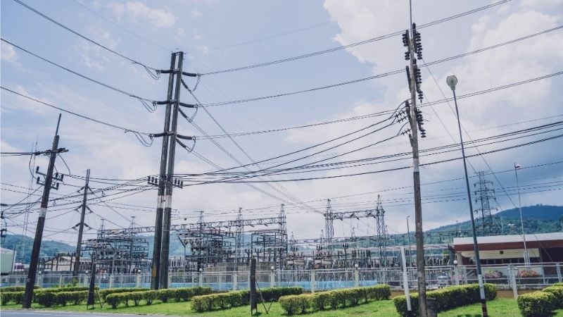
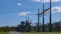
Substation and transmission lines. Image used courtesy of Adobe Stock
Primary Distribution’s Role in the Power System
Positioned between the high-voltage grid and secondary networks, primary distribution delivers medium-voltage power across neighborhoods, industrial parks, campuses, and towns.
Substations, often supplied from 69-115 kV or similar, host step-down transformers, buswork, and protection that feed multiple primary circuits. The substation-to-feeder relationship determines service territory geometry and operating flexibility: multiple feeders from a single bus supply adjacent areas, and normally open ties between neighboring feeders enable switching for maintenance or contingency restoration.
In North America and many other regions, nominal primary voltages commonly selected by utilities include 12.47/7.2 kV, 13.8 kV, 24.9 kV, and 34.5 kV, while 11 kV and 33 kV remain prevalent in many 50 Hz systems. Selection typically reflects historical standards, insulation class, and desired reach and capacity for a given geography.
A central aim of primary design is service continuity. Protection, switching points, and alternate-source ties are arranged so that temporary faults are cleared and sustained faults are isolated with minimal impact. Economic use of conductor cross-section is another aim, balancing capital cost against energy losses and voltage performance across the planning horizon.
Substation automation and feeder automation add further flexibility by isolating faulted segments and restoring healthy sections through remote switching. Field experience shows that distribution automation schemes can isolate a faulted section and restore adjacent segments in minutes by closing an alternate feeder tie, improving reliability indices and service quality.
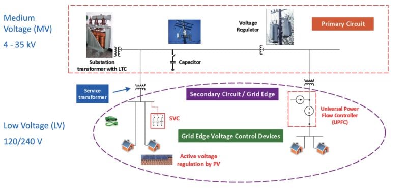
Figure 1. Primary and secondary distribution system. Image used courtesy of National Renewable Energy Laboratory
Feeders and Laterals: Configuration and Loading
Feeder Structure
A primary feeder is the medium-voltage circuit originating at a distribution substation and extending outward to serve distribution transformers and local switching points. Main feeders are the backbone three-phase circuits; laterals are taps—often single- or two-phase—that branch from the main to reach clusters of load along streets, cul-de-sacs, or rural lines.
Typical lengths vary substantially with geography. Average three-phase feeder lengths are around 10.8 miles, while rural 24.9 kV circuits may extend 40-50 miles in one direction where load density is low. Urban feeders tend to be shorter and meshed through normally open ties; rural circuits are longer and more radial.
Topology choices reflect operating philosophy and cost. Radial arrangements—single source, branches that do not rejoin—are simpler and cost-effective but require more switching to restore unfaulted segments after a permanent fault. Looped or “open-loop” arrangements interconnect two sources with a normally open point in the middle, permitting backfeed of healthy sections after isolation.
Pad-mounted or RMU-based loop schemes are common in underground networks, while overhead systems may combine radial feeders with sectionalizing and tie points.
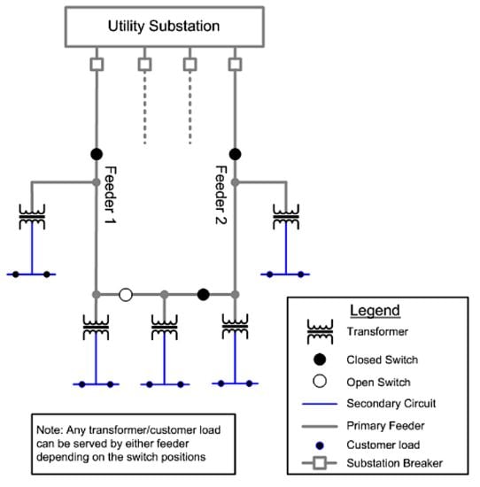
Figure 2. Radial distribution system. Image used courtesy of NREL
Feeder Loading Characteristics
Loading along a feeder is inherently diverse. Residential peaks often occur in evening hours, commercial peaks in daytime, and industrial profiles vary by process, yielding diversity that allows more connected kVA than the feeder’s coincident peak.
Utilities typically define practical capacity limits by thermal ratings of conductors, equipment ratings, and planning “economic” limits. For example, one utility’s planning benchmark approximates 600 A as a practical limit, translating to about 15 MVA on 13.8 kV and roughly 37 MVA on 34.5 kV feeders under favorable conditions. Utility planning guidance often cites typical feeder ratings near 12 MVA for 13.8 kV and 30 MVA for 34.5 kV, recognizing that conductor size, ambient conditions, and protection constraints govern actual limits.
Two planning quantities frame both the day-to-day operation and long‑term reinforcement triggers. Peak demand sets conductor and device thermal constraints, while load factor indicates how steadily the feeder is utilized:
$$\text{Load Factor} = \frac{\text{Average Load}}{\text{Maximum Load in Given Time Period}}$$
Higher load factor improves loss performance and defers upgrades; lower load factor can point to peaky profiles that stress voltage drop and thermal margins during short windows. Forecasts combine historical weather-normalized peaks, DER additions, and land-use changes to anticipate growth and voltage performance at feeder extremities.
Feeder Design Considerations
Three linked criteria drive conductor selection:
- Thermal limit: Ampacity must exceed expected maximum current with a margin for contingencies and ambient conditions.
- Voltage performance: Acceptable drop to the remote end under peak and contingency flows.
- Economics: A conductor that minimizes the sum of capital and lifetime loss cost over the planning horizon.
Voltage regulation on distribution circuits is frequently analyzed with the well-known approximate drop formula based on R and X with load power factor. For phase-to-neutral quantities, a widely used expression is:
$$\Delta V \approx 2 \times I \times [R \cos(\phi)~+~X =sin(\phi)] \times L $$
and for three-phase line-to-line voltage drop, a common form is:
$$\Delta V_{3\phi} \approx \sqrt{3} \times I \times [R \cos(\phi)~+~X =sin(\phi)] \times L $$
where I is current, R and X are per‑unit‑length resistance and reactance, φ is load power‑factor angle, and L is length. Designers also work with percent drop forms and single‑phase approximations in utility handbooks.
Typical practice applies design targets inspired by codes and utility standards for low‑voltage end users. Although the NEC contains informational notes rather than prescriptive feeder targets, many specifications apply about 2-3% for feeders and 5% total feeder-plus-branch within secondary systems.
For primary circuits, utility standards specify their own feeder-end voltage windows and control devices—line regulators, capacitor banks, and transformer taps—to maintain service voltage at secondaries. On long rural feeders, managing drop may require upsizing the conductor, converting to a higher primary voltage class such as 12.47 to 24.9 kV, installing mid‑point voltage regulators, and deploying switched capacitors to support reactive power.
Economic conductor sizing blends thermal, voltage, and lifecycle-loss costs. Kelvin’s classic formulation states that the most economical cross‑section occurs where annual carrying charges that scale with conductor size equal the annual cost of I²R losses. Modern approaches extend this by considering energy price forecasts, demand charges, and probabilistic load growth. Rural utilities and planning guides describe structured methods that weigh conductor inventory, voltage constraints, and long‑run losses to select sizes, feeder‑segment by feeder‑segment.
Lateral Design
Laterals connect local transformer clusters and single‑phase taps to the three‑phase backbone. Their design emphasizes simplicity, visibility, and selectivity. Protection should clear lateral faults without tripping the main feeder breaker or upstream reclosers whenever possible. In overhead systems, downstream fuses protect laterals and transformer taps. On underground networks, pad‑mounted switchgear and sectionalizing cabinets provide equivalent functions.
Coordination between feeder protection and lateral fuses relies on time‑current curve separation, so a lateral fuse clears for faults on its segment before upstream devices operate. Fuse‑saving philosophies permit a fast trip and reclosing upstream to let transient faults clear before a fuse melts. Where permanent faults dominate, fuse‑blowing philosophies avoid unnecessary upstream operations.
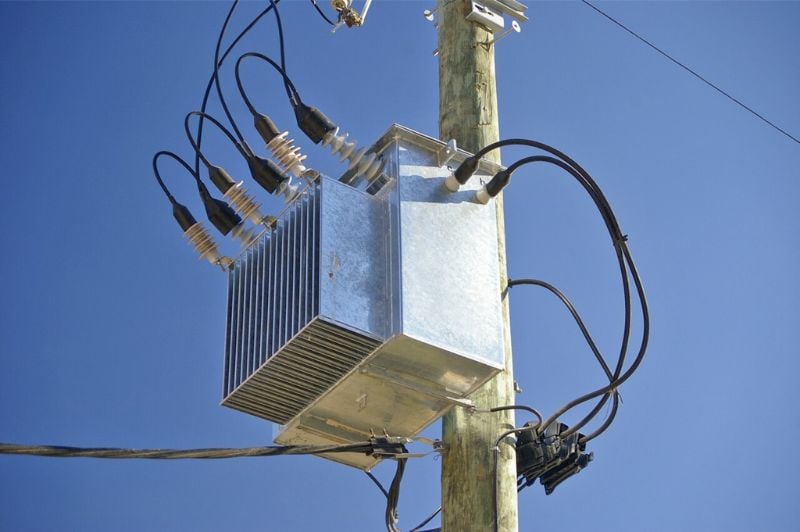
Figure 3. Pole-mounted distribution transformer. Image used courtesy of Wikimedia Commons
Sectionalization strategies divide feeders into zones using reclosers and sectionalizers. Reclosers interrupt fault current and then reclose to test whether a fault is transient. Sectionalizers count upstream operations and open during a recloser’s open interval, isolating the faulted section without interrupting higher-level protection coordination.
Modern cutout‑mounted reclosers at lateral takeoffs blend fuse and recloser characteristics, improving restoration options and limiting patrol lengths. Automated schemes, informed by communications and feeder state awareness, can isolate a faulted span and restore healthy sections via normally open ties in minutes, significantly improving SAIDI/SAIFI outcomes.
Table 1. Common primary voltage classes and indicative feeder capacities
| Nominal primary voltage | Indicative thermal/planning capacity (MVA) | Notes |
| 4.16 kV | ~4 MVA | Typical value cited for older low-voltage primaries. |
| 12.47/13.8 kV | ~12-15 MVA | Utility benchmarks show about 12 MVA typical; some plan ~15 MVA depending on conductor and 600 A limits. |
| 22–24.9 kV | ~20 MVA | Supports longer reach and improved voltage performance. |
| 34.5 kV | ~30-37 MVA | Higher capacity and reach; planning guides cite ~30 MVA typical and ~37 MVA under favorable conditions. |
Table 2. Typical feeder geometries and lengths
| System type | Typical geometry | Indicative length |
| Urban/suburban | Shorter, multiple ties, underground or overhead | Average three-phase feeder ≈ 10.8 miles (varies by utility). |
| Rural | Long radial with sectionalizing, some looped underground in towns | Can extend 40–50 miles in one direction at 24.9 kV class. |
Putting It Together in Planning
In practice, planners begin with a forecast peak and a daily profile to compute loading and load factor for each feeder. With a nominated voltage class and conductor inventory, power‑flow studies check end‑of‑line voltage and thermal margins for normal and contingency states.
Where voltage is marginal, options include a larger conductor on the remote sections, switched capacitors for kVAr support, line regulators, or a higher primary voltage conversion if justified by growth and distance. Where thermal headroom is limited, reconductoring, feeder splitting from a new or expanded substation position, or reconfiguration to balance loads across adjacent feeders may be appropriate.
Economic analyses weigh conductor capital costs against lifetime I²R losses using Kelvin’s principle so that the chosen cross‑section is cost‑effective for the expected duty cycle and planning horizon.
Protection and switching layouts are then coordinated so lateral devices clear local faults without tripping the entire circuit, while feeder‑level reclosers, breakers, and automation restore unaffected sections quickly. Modern distribution automation field experience demonstrates that isolating a faulted segment and reclosing a normally open tie to backfeed healthy sections can restore hundreds of customers within minutes, even before a field crew reaches the site. Such schemes depend on well‑placed sectionalizing devices, accurate time‑current coordination, and communications to substation and field devices.
Conclusion
Primary distribution systems translate bulk power into serviceable medium‑voltage circuits that can reach widely varying load densities while maintaining acceptable voltage and reliability. Effective designs start with a suitable voltage class and feeder topology for the geography, then select conductors that meet thermal and voltage criteria while controlling lifecycle losses. Load diversity and load factor inform practical capacity limits and reinforcement timing.
Voltage regulation relies on impedance‑based drop analysis, reactive support, and regulators positioned where they deliver the most benefit. Finally, selective protection—fuses on laterals, coordinated reclosers and sectionalizers on the backbone, and automated switching—limits the footprint of faults and restores unaffected segments rapidly. With these elements aligned, feeders and laterals deliver reliable, economical service from the substation bus to the distribution transformer across both dense urban grids and long rural lines.


Great information shared in this blog. Choosing the right Copper Bonded Earth Electrode Manufacturer is extremely important for safe and efficient electrical grounding. We checked SG Power Copper Bonded Earth Electrode
and found their earthing products engineered for high conductivity and long-term durability. Copper bonded electrodes help reduce maintenance costs and improve electrical safety standards. Their products are suitable for industrial, commercial, and infrastructure projects. Thanks for sharing such valuable knowledge about modern earthing systems.