Facebook
 Google
 GitHub
 Linkedin
Practical Application of Middlebrook Filter Criteria
In this article, we will revisit a very old topic and apply practical rules to the problem. The subject is the stability of a system where an input filter interacts with a switching power supply.
This article discusses how defining the input filter incorrectly can lead to inaccurate conclusions about system stability or lead to systems that are far from optimal. We will demonstrate the need to properly identify which components are part of the input filter and which are part of the power supply. Middlebrook’s input filter stability criteria only apply to the system measured with the filter components in the correct location.
Then, we will talk about the practical way to measure the system. Complex and difficult measurements can be avoided with a pragmatic and simple lab approach to ensure a stable system.
Input Filter Impedance Interaction
An input impedance measurement or prediction gives information about the characteristics of the power supply input terminals. Knowledge of the input impedance characteristic is very useful for anyone who must add components to the basic power supply design to complete the power system. This can include an input EMI filter or another power supply that preconditions the input voltage rail.
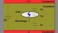
Figure 1 shows a block diagram of a switching power supply connected to an input filter. Dr. Middlebrook, in his paper on input filter interactions [1], said that if the input impedance of a converter, Zin, is always greater than the output impedance of the filter, Zout, then a stable power supply will remain stable when the filter is connected.
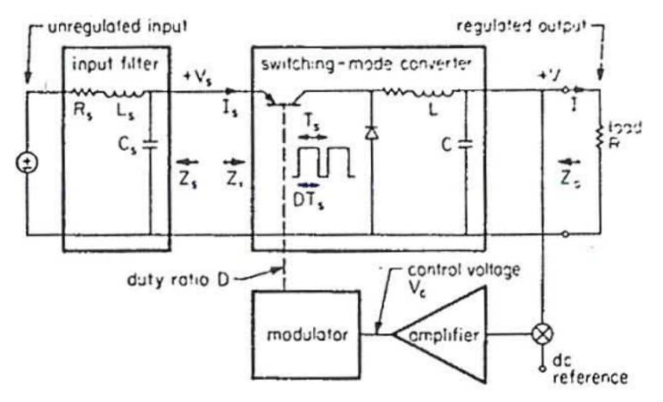
Image used courtesy of Bodo’s Power Systems [PDF]

Figure 1. Power supply with input filter module. (Middlebrook’s original Figure 1 is shown for reference.). Image used courtesy of Bodo’s Power Systems [PDF]
Conceptually, the impedances can be measured with the setup shown in Figure 2. An AC voltage source is connected in series between the filter and the switching power supply. The input impedance of the power supply is measured from the ratio of the input voltage of the switching power supply and the current into the terminals. While this measurement is easy to conceive and implement in a theoretical circuit or simulation, it is an awkward measurement to make in the lab. As we will see in this article, it will often result in erroneous results if you don’t measure in the right place.
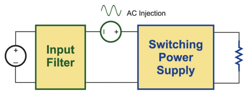
Figure 2. Voltage injection into the power rail for impedance interaction measurements. Image used courtesy of Bodo’s Power Systems [PDF]
Measuring in the Right Place
The Middlebrook criteria requires that the switching power supply block of Figure 2 contains only the switching cell and none of the input filter components, as shown in his original Figure 1. However, it is usually a practical necessity that at least one filter component is included in the power supply block to filter high-frequency pulsating currents. Without this, measurements can be too noisy, and the converter may not operate properly. Also, in many cases, the internal circuit nodes for measurement are inaccessible, and the power supply input impedance measurement will naturally include several filter components.
Figure 3 shows a measurement setup where a small input bypass capacitor is included in the power stage measurements. This has a significant impact on the input impedance measurements, greatly reducing the impedance at higher frequencies. We cannot use this measurement to apply the Middlebrook criteria.

Figure 3. Flyback converter with input filter capacitor. In most cases, practical measurements require some input filter components to be included in the impedance measurement. Image used courtesy of Bodo’s Power Systems [PDF]
Figure 4 shows the proper location for the application of the Middlebrook criteria. The filter capacitor is moved into the input filter block and is NOT included in the switching power supply block. However, it is included in the filter block.
Now we have a problem. Proper application of Middlebrook’s rule requires that we measure the system of Figure 4, but it may be practically impossible to measure the input impedance. If we just measure the input impedance of the power supply with filter components inside, Middlebrook’s rule has no relevance. What to do? The answer is considered next in this article.
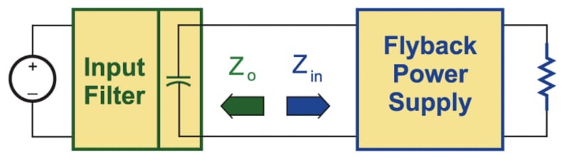
Figure 4. Proper characterization of the impedance interaction requires the input filter capacitor to be moved to the filter module. Image used courtesy of Bodo’s Power Systems [PDF]
Plot the Measured Output Impedance of the Unpowered Input Filter
Measure the output impedance of the input filter, including all filtering components, with a device such as the AP310, or the RidleyBox. This measurement can be done with the filter unpowered, making sure that the input of the filter is shorted. This is an easy measurement to make since there is no switching noise present.
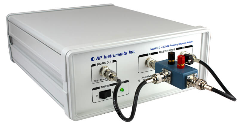
Figure 5. Use the AP310 or the RidleyBox to measure the unpowered input filter. This measurement is essential since filter vendors may not provide accurate data or measurements. Make sure the input of the filter component block is shorted. Image used courtesy of Bodo’s Power Systems [PDF]
We don’t recommend that you just model the input filter in a circuit simulator–always confirm the impedance with measurement. It is common for filter designers to use core loss and damping components to stop the input filter impedance from peaking. The damping mechanisms require advanced circuit models that are unlikely to be provided by a filter vendor. There is no problem in using your circuit simulator to verify the results, but you should always make a hardware measurement.
Plot the Calculated Ideal Input Impedance of the Power Supply
There is no need to measure the input impedance of the power stage. This can be plotted as a theoretical quantity. For simplicity and to be conservative in the design, we will assume an infinite bandwidth control loop which will provide a fixed negative input impedance.
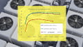
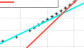
The two impedances are plotted on the same graph, as shown in Figure 6. Make sure there is good separation (10 dB) between the two quantities.
You can see from Figure 6 that this is a poor design without good separation of input and output impedance. Even if there is good separation, it is a good idea to damp the ringing of the filter to prevent ringing at the output of the power filter. I remember Middlebrook stating at a conference that it’s probably not a good idea to run with an undamped filter.
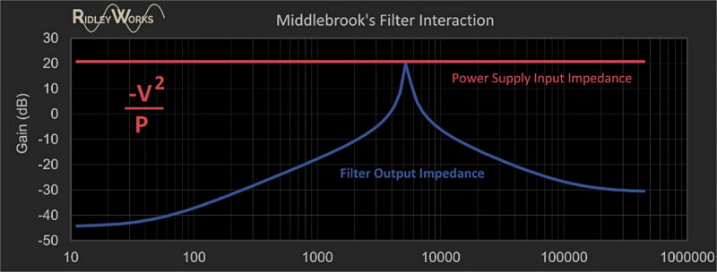
Figure 6. Measured filter output impedance plotted with calculated power supply input impedance. The example shown here is NOT a good design case. It will probably oscillate. Image used courtesy of Bodo’s Power Systems [PDF]
In the practical world, there is no need to consider the open-loop input impedance of the power supply. Middlebrook devoted a lot of time in his paper to talking about this, but I have never seen it applied in the field.
6 Steps to Successful System Design
Middlebrook’s original paper is quite complicated to follow. However, bear in mind that it is an academic paper. Simplify for practical application. There are six steps to a successful system design:
1. Identify the components that are part of the input filter.
2. Identify the components that form the switching power supply. Do not include any filter components in the power supply.
3. Place a short circuit on the input to the filter.
4. Measure the output impedance with a device such as the AP310 or RidleyBox. Use the impedance attachment. This is a passive, two-terminal measurement that does not require power applied to the input filter.
5. Plot the calculated input impedance of the power converter on the same graph as the filter output impedance. Ensure good separation between the two curves.
6. Check that the filter is well-damped to prevent ringing. Failure to do this can cause dynamic range loss in the operation of the power system.
Following these steps will bring confidence in rendering a stable system.
References
- Input Filter Considerations in Design and Application of Switching Regulators 1976 paper by Dr. R.D. Middlebrookk
- Impedance Measurement for Switching Power Supplies using the AP310 or RidleyBox frequency response analyzers.
- Input Filter Design and Measurement, and other related articles in the Ridley Engineering Design Center.
This article originally appeared in Bodo’s Power Systems [PDF] magazine.
Related Content