Facebook
 Google
 GitHub
 Linkedin
Practical Guidelines for Litz Wire Selection and AC Copper Losses Estimation Part 1
Applied to Resonant Power Magnetics used in Automotive Converters.
Litz wire conductors are well known and massively used in magnetic components dedicated to power electronic applications to reduce copper losses versus frequency. However, their modelization could remain complex or not fully fixed for an accurate prediction of the final temperature rise in the windings of switching transformers or resonant inductors. The best wire selection and accurate computing of its losses remain in the first position for high power density converters optimization.
The increasing market of electrical and plug-in hybrid vehicles requires powerful embedded switch-mode power supplies (figure 1), including large inductive devices as well as AC/DC high voltage battery chargers of some 7-11-22kW (figure 2a) and DC/DC 400-800V/14V converters of a few kW (figure 2b) to supply in energy conventional low voltage equipment (lighting and air-conditioning systems, ECUs, radio-set, GPS, etc.).
The magnetic components used in such power electronic assemblies generally count for 1/4th to 1/3rd in volume, weight, and cost within such devices. Therefore, their optimization in terms of power density is fully mandatory till the limit of an acceptable efficiency and temperature rise depends also on the cooling strategy [1]. For transformers and inductors used in such parts, low-loss ferrite cores and Litz wire windings are mostly selected. The best Litz wire selection remains a must for copper loss reduction versus frequency.

Figure 1. 7-11kW OBC + 2.4kW/14V DCDC presented by BOSCH Mobility Solutions [2]. Image used courtesy of Bodo’s Power Systems [PDF]
This article will first summarize the well-known properties of Litz wire by highlighting special care and tips in its selection (part 1). The modelization approach of such conductors will be then discussed and the models available in FEA simulation tools will be compared. Eventually, a few words and references about the equivalent thermal conductivity that can be assigned to a given Litz wire will be introduced to help in thermal simulation (part 2).
Litz Wire Advantage and Selection
Frequency Impact on the Wire Choice
Why Litz wire for conductors? It is well known that frequency effects in a metal can affect a lot of the losses in it when carrying an alternating current. Three major effects are identified as eddy currents, proximity effect, and fringing flux effect. The first is related to the self-induced magnetic field around a conductor that generates eddy currents circulating principally on its outer surface to try to cancel the effect that has given life to it (figure 3a). The proximity effect is something similar but related to the same effect in conductors in the neighborhood (figure 3b). Each turn perturbates the surrounding ones and is also influenced by them. The third effect can be related to the presence of any external magnetic field with time variation as is the case from airgaps cut in cores to fix some precise inductance value (figure 3c).

Figure 2a. PREMO 11kW CLLLC magnetic module before potting. Image used courtesy of Bodo’s Power Systems [PDF]

Figure 2b. PREMO HV/LV 2kW DCDC transformer as a ready-to-plug solution. Image used courtesy of Bodo’s Power Systems [PDF]

Figure 3a. Eddy currents. Image used courtesy of Bodo’s Power Systems [PDF]

Figure 3b. Proximity effect. Image used courtesy of Bodo’s Power Systems [PDF]

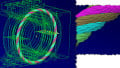
Figure 3c. Current density inside a conductor including the fringing flux effect from an air gap. Image used courtesy of Bodo’s Power Systems [PDF]
A key parameter to quantify this perturbating current distribution over the surface of the conductor is the skin depth expressed below (figure 4). It is well admitted that the first choice for the conductor diameter must always remain below 2δ (dconductor < 2δ) not to see a noticeable increase in its resistance. For instance, an easy calculation at 7δ diameter leads to twice the DCR value (figure 5).

Figure 4. Skin depth in copper (apply 6.6 instead of 7.5 coefficient at 100°C). Image used courtesy of Bodo’s Power Systems [PDF]

Figure 5. 7δ Diameter Conductor shows an AC Resistance of twice the DC value. Image used courtesy of Bodo’s Power Systems [PDF]
The above considerations are valid for a single conductor. However, these simple formulas and concepts clearly illustrate that according to the current to drive through the winding, parallelization of small conductors will be a must. They can be just wound multi-filar that it is not a good solution either for proximity effect between conductors or process optimization. Litz wire characterizes this parallelization plus a twisting versus length so that each strand passes equally through each position on the inside and outside of the bundle (figure 6). This prevents the circulation of currents between strands by reducing proximity effects.

Figure 6. Litz wire for proximity effect reduction between thin strands. Image used courtesy of Bodo’s Power Systems [PDF]
It is particularly true when the component is submitted to a high-frequency switching with high current variations (for example resonant chokes with full wave excitation). Of course, other design considerations will be important to reduce the copper losses at the minimum, such as the winding structure (bifilar, concentric, multi-level interleaving…) or the core design (single or multigap…).
From a practical standpoint, it is not always easy to quantify the increase of copper losses versus frequency. For a 2-winding transformer, it can be possible to have an overview of the total AC copper losses by measuring its impedance versus frequency viewed from the primary side with the secondary shorted. Here, the core has normally no influence on the Rac measurement (ampere-turns cancelation or with remaining fully negligible magnetic induction) which is not the case for single chokes where such measurement must be taken with a lot of precaution because of a representative of core+copper losses at the end.
Below is an example considering a 2.3mm Litz wire diameter of different strandings (figure 7). We can clearly notice the improvement in the 100-200kHz operating region when the strand is of a lower diameter even if in some cases it could lead to higher estimated DC losses. As a matter of fact, the total copper cross-section can differ according to the number of strands assembled for the same overall diameter. So, a compromise to find can exist between the strand's thickness and the number to twist together.

Figure 7. AC copper losses in a transformer acc. to the Litz wire selection. Image used courtesy of Bodo’s Power Systems [PDF]
Fr = Rac/Rdc is a coefficient of interest that could be set as a design rule for given technologies and stranding (table 1). It shows the increase of copper losses vs. frequency depending on the wire and winding arrangements. The below table proposes some coefficients that can be applied for the total copper losses estimation with a good Litz wire selection for the windings. Of course, if the harmonics content of the current waveform is high, a more accurate study shall be performed.
Table 1. Optimized Fr coefficients for some given topologies/technologies.
| Transformer Type with Optimized Litz Strand | OBC LLC 3.5kW | DCDC HV/LV PSFB ZVS 3kW – 1x Interleaving | DCDC HV/LV PSFB ZVS 3kW – 2x Interleaving |
| Fr = Rac/Rdc | 1.2 to 2 @100- 250kHz | 3 to 5 @100- 150kHz | 2 to 3 @100- 150kHz |
The strand diameter selection can have a big impact on the real total AC copper losses of transformers or chokes wound by Litz wire. From such statements, the strand diameter must be optimized to keep the Fr ratio as low as possible without maximizing the cost of the product by expensive Litz wire application or too challenging an interleaving process in the winding construction.
Generally speaking, and because of the skin effect, the higher the operating frequency, the thinner the nominal single-wire diameter.
The Litz wire suppliers [3] often propose a table of recommended use according to the frequency range (table 2). It can be good to introduce some margins to consider the possible harmonics content of the current waveform which could be high for phase-shift half- or full-bridge ZVS topologies as well as for LLC/CLLLC in some cases.
Table 2. Strand diameter selection for Litz wire.
| Range of Frequency (kHz) | Nominal Diameter of Single Wire (mm) | ||
| From | To | From | To |
| 0.06 | 1 | 0.4 | 0.25 |
| 1 | 10 | 0.25 | 0.2 |
| 10 | 20 | 0.2 | 0.125 |
| 20 | 50 | 0.125 | 0.1 |
| 50 | 100 | 0.1 | 0.08 |
| 100 | 200 | 0.08 | 0.063 |
| 200 | 350 | 0.063 | 0.05 |
| 350 | 850 | 0.05 | 0.04 |
| 850 | 1400 | 0.04 | 0.03 |
| 1400 | 3000 | 0.03 | 0.02 |
In Litz wires, to consider a minimum interaction between several bundle diameters with δ skin depth, and in a simplified way, the maximum single wire diameter should be smaller or equal of nearly a third of δ (dstrand < δ/3). Example: F = 200kHz, δ = 0.148mm => dstrand ≈ 0.050mm.
Current Density and Number of Strands
When the strand diameter is selected, the number to consider will depend on the acceptable current density in the windings of the magnetic devices. Even if the total copper losses and the hotspot temperature shall be determined afterward, some additional design rules can be preliminary applied to confirm a possible diameter of the final conductor to use (table 3).
Construction
Litz wires cannot be only defined by the stranding. Other parameters of importance are the bunching and the twisting (table 4). As a matter of fact, the bunching (ex. : 50x5 vs. 10x5x5…) and its direction (S or Z at different levels) could affect a lot the frequency behavior (figure 8). The twisting (number of rotations per meter or lay length or pitch) is normally calibrated to have at least 3 rotations along the mean turn length of the winding; this is to balance the best proximity effect cancellation.
Table 3. Applicable current density per size and cooling.
| Component Type and Cooling Concept | J (A/mm²) |
| Big Power (tens of kW)Transformer, No Cooling | 2-3 |
| Big Power (tens of kW) Transformer, Air-blow | 3-6 |
| kW-range Transformer fixed on a Water-cooled Plate | 7-10 |
| Fully Potted Transformer in a Water-cooled Cavity | 10-15 |
Table 4. Example of Litz wire complete specification (source: SUNTEK WIRE)
| Conductor | Bare wire diameter (mm) | 0.10 |
| Tolerance (mm) | ±0.003 | |
| No. Of strand | 250 | |
| Bunching | 50x5 | |
| Single wire | Enamel Thickness (≥mm) | 0.008 |
| overall diameter (≤mm) | 0.117 | |
| Litz wire | No. of lay (Ts/m) | 30±5 |
| Lay direction | S | |
| Taped wire | Overlap [%] | 67±3 |
| Max. overall diameter (≤mm) | 2.287 | |
| Break - down Voltage (≥v) | 4000 | |
| Film layer thickness for two sides (mm) | 0.15 | |
| Width of the tape (±0.5mm) | 12 | |
| Thickness of the film (±0.003mm) | 0.025 | |
| Electric Resistance DC (≤Ω/km, 20°C) | 9.61 | |

Figure 8. Litz wire bunching and twisting. Image used courtesy of Bodo’s Power Systems [PDF]
Some rules can be applied for the bunching definition. The maximum number of strands at first bundle level (N1,max) can be given by the below formula [4] where δ is the skin depth at the defined operating frequency and temperature, and ds is the selected strand diameter:
\[D=\sqrt{N_{s}.}d_{s}.\rho\]
With D the overall diameter of the Litz wire, ds the diameter of the strands, and p the packing factor for Ns strands.
Table 5a. Packing factors for different number of strands (source: ELEKTRISOLA)
| Elektrisola Packing Factors | |
| # of Wires Factor | |
| 3 - 12: 1.25 | |
| 16: 1.26 | |
| 20: 1.27 | |
| 25 - 400: 1.28 |
Another parameter that will impact the overall diameter is the type of insulation. The following section will be dedicated to the presentation of the different technologies, possible application, and advantages of each.
Isolation and Certifications
When the copper distribution is fully defined for the best performance in the application, criteria for the isolation must be added. Of course, the strands are isolated as common enameled wires and the same standard and grades applied. Thermal class is F/155°C or solderable H/180°C according to IEC 85 in most of the cases. Varnish thickness is normally according to grade 1 to offer a limited overall diameter as well as an easier solderability when connecting all the strands together at the outputs (by tinning, electrical soldering, or hot-crimping methods…).
Table 5b. Packing factor for different Litz wire structures (source: RUBBADUE)
| Litz Construction | Single End Wire Size | Packing Factor |
| n/## | 48-20 AWG | 1.155 |
| n/n/## or n/n/n/## | 48-33 AWG | 1.155 |
| 5xn/## or 3xn/## | 48-20 AWG | 1.236 |
| 5xn/n/## or 3xn/n/## | 48-33 AWG | 1.236 |
| 5x5xn/## or 5x3xn/## | 48-44 AWG 43-33 AWG 32-20 AWG |
1.271 |
| 1.328 | ||
| 1.398 | ||
| 5x5xn/n/## or 5x3xn/n/## | 48-44 AWG 43-33 AWG |
1.271 |
| 1.363 | ||
| 5x5x5xn/## or 5x5x3xn/## | 48-44 AWG 43-33 AWG 32-20 AWG |
1.271 |
| 1.363 | ||
| 1.536 | ||
| 5x5x5xn/n/## or 5x5x3xn/n/## | 48-33 AWG | 1.363 |
| n = Number of Strands in bunch | ## = AWG Size of individual strands | |
Litz wire often offers a serving for protection or enhanced isolation between turns, layers, or windings (figure 9). It could be:
- A serving of a single or double layer of silk or nylon if the self-isolation of the strand by enamel could be not enough. This is the cheapest and most suitable choice for low-withstanding voltages. When using this type of wire, varnishing the winding or even the finished product can help because the silk or nylon textile can absorb the varnish and provide more robust isolation. Applying the varnish under the vacuum process would be preferred to improve reliability and reproducibility.

Figure 9. Served/taped/extruded Litz wires from ELKTRISOLA manufacturer. Image used courtesy of Bodo’s Power Systems [PDF]
- An overlapping by tape, which can be PET/PEN/Mylar/polyimide... These wires can achieve better dielectric strengths. The definition of the insulating film will depend on the thermal class and required dielectric strength. The overlapping is one of the parameters that can be modified to fix the performance. At 50%, it enables 2 layers of isolation at any length on the wire whereas a tighter 67% overlapping leads to 3 layers. These overlapping techniques are a way to answer to safety standards that require multi-layer of thin film isolation (IEC 60950-1, IEC 61558- 1/-2-16…). Some well-known suppliers even propose fully VDE or UL-certified construction according to this technique [6].
- It exists other isolation structures by plastic extrusion around the conductor [7]. It can be made of Teflon, polyester or of any other suitable material. Here also, 2-layer or 3-layer extrusion can be imagined as in double-insulated (DIW) or triple-insulated wires (TIW).
Cost Consideration in Automotive Industry
The use of Litz wire in wire wound products increases cost and decreases the amount of copper within the core window. Depending on the expected performances vs. frequency and level of isolation it could have a huge weight in the cost breakdown of the final product [8]. However, it remains today the first choice in resonant wire-wound inductive components used in some kW to tens of kW automotive converters where heating and efficiency come always under the scope of power density increase.
This article is the first one in a two-part series.
This article originally appeared in Bodo’s Power Systems [PDF] magazine.
Related Content